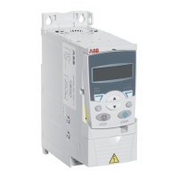
84 Control panels
Copy mode
The basic control panel can store a full set of drive parameters and up to three user
sets of drive parameters to the control panel. Uploading and downloading can be
performed in local control. The control panel memory is non-volatile.
In the Copy mode, you can do the following:
• Copy all parameters from the drive to the control panel (uL – Upload). This
includes all defined user sets of parameters and internal (not adjustable by the
user) parameters such as those created by the ID run.
• Restore the full parameter set from the control panel to the drive (dL A –
Download all). This writes all parameters, including the internal non-user-
adjustable motor parameters, to the drive. It does not include the user sets of
parameters.
Note: Only use this function to restore a drive, or to transfer parameters to
systems that are identical to the original system.
• Copy a partial parameter set from the control panel to a drive (dL P – Download
partial). The partial set does not include user sets, internal motor parameters,
parameters 9905…9909, 1605, 1607, 5201, nor any group 51 EXT COMM
MODULE and 53 EFB PROTOCOL parameters.
The source and target drives and their motor sizes do not need to be the same.
• Copy user set 1 parameters from the control panel to the drive (dL u1 – Download
user set 1). A user set includes group 99 START-UP DATA parameters and the
internal motor parameters.
The function is only shown on the menu when user set 1 has been first saved
using parameter 9902 APPLIC MACRO (see section User macros on page 119)
and then uploaded to panel.
• Copy user set 2 parameters from the control panel to the drive (dL u2 – Download
user set 2). As dL u1 – Download user set 1 above.
• Copy user set 3 parameters from the control panel to the drive (dL u3 – Download
user set 2). As dL u1 – Download user set 1 above.
• Start, stop, change the direction and switch between local and remote control.
4. Select the scalings for the signals by specifying the
minimum and maximum display values. This has no
effect if parameter 3404/3411/3418 is set to 9
(DIRECT). For details, see parameters 3406 and
3407.
Signal 1: parameters 3406 OUTPUT1 MIN and 3407
OUTPUT1 MAX
Signal 2: parameters 3413 OUTPUT2 MIN and 3414
OUTPUT2 MAX
Signal 3: parameters 3420 OUTPUT3 MIN and 3421
OUTPUT3 MAX.
Step Action Display

 Loading...