Actual signals and parameters 205
14 RELAY OUTPUTS Status information indicated through relay output, and relay
operating delays.
Note: Relay outputs 2…4 are available only if the MREL-01
output relay module is connected to the drive. See MREL-
01 output relay module user's manual (3AUA0000035974
[English]).
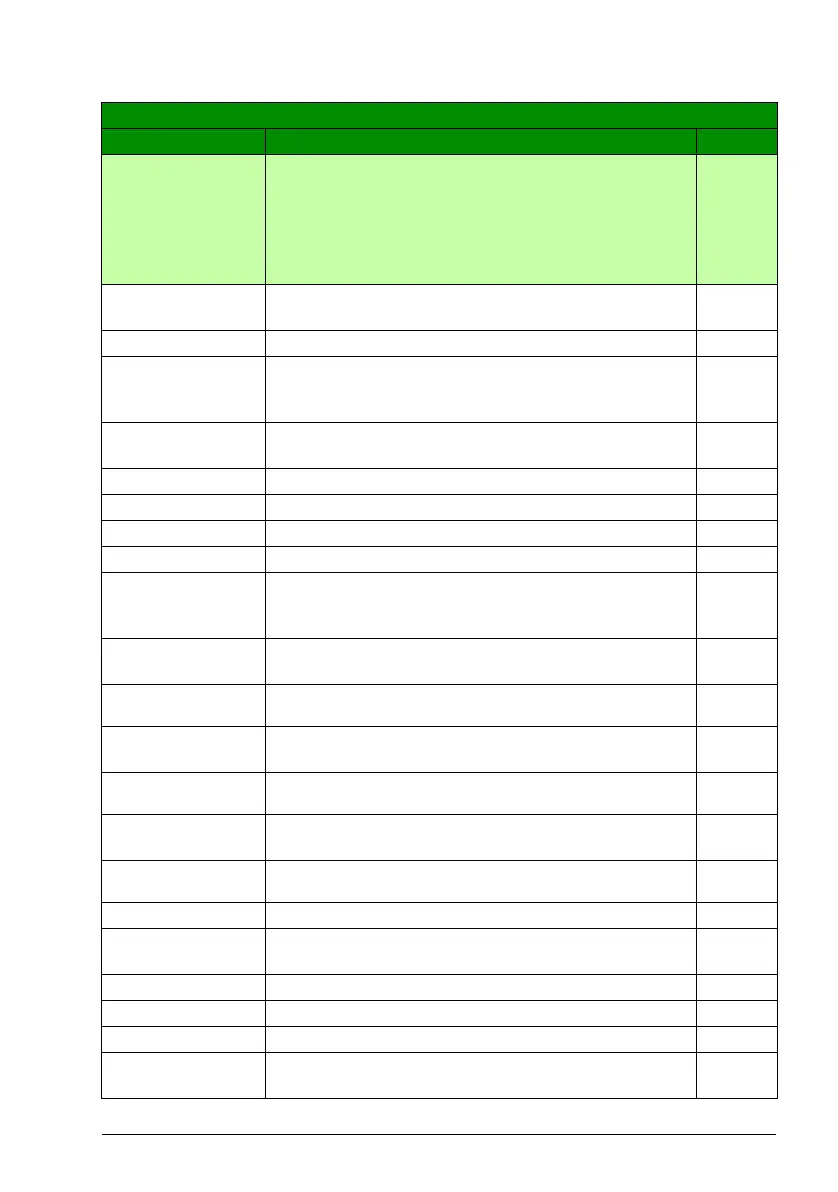
1401 RELAY
OUTPUT 1
Selects a drive status indicated through relay output RO 1.
The relay energizes when the status meets the setting.
FAULT(-1)
NOT SEL Not used 0
READY Ready to function: Run enable signal on, no fault, supply
voltage within acceptable range and emergency stop signal
off.
1
RUN Running: Start signal on, Run enable signal on, no active
fault.
2
FAULT(-1) Inverted fault. Relay is de-energized on a fault trip. 3
FAULT Fault 4
ALARM Alarm 5
REVERSED Motor rotates in reverse direction. 6
STARTED The drive has received start command. Relay is energized
even if Run enable signal is off. Relay is de-energized when
drive receives a stop command or a fault occurs.
7
SUPRV1
OVER
Status according to supervision parameters 3201…3203.
See parameter group 32 SUPERVISION.
8
SUPRV1
UNDER
See selection SUPRV1 OVER.9
SUPRV2
OVER
Status according to supervision parameters 3204…3206.
See parameter group 32 SUPERVISION.
10
SUPRV2
UNDER
See selection SUPRV2 OVER.11
SUPRV3
OVER
Status according to supervision parameters 3207…3209.
See parameter group 32 SUPERVISION.
12
SUPRV3
UNDER
See selection SUPRV3 OVER.13
AT SET POINT Output frequency is equal to the reference frequency. 14
FAULT(RST) Fault. Automatic reset after the autoreset delay. See
parameter group 31 AUTOMATIC RESET.
15
FLT/ALARM Fault or alarm 16
EXT CTRL Drive is under external control. 17
REF 2 SEL External reference REF 2 is in use. 18
CONST FREQ A constant speed is in use. See parameter group 12
CONSTANT SPEEDS.
19
All parameters
No. Name/Value Description Def/FbEq

 Loading...


