Electrical installation 55
Connection examples of two-wire and three-wire sensors
Hand/Auto, PID control, and Torque control macros (see section Application macros,
pages 114, 115 and 116, respectively) use analog input 2 (AI2). The macro wiring
diagrams on these pages use an externally powered sensor (connections not shown).
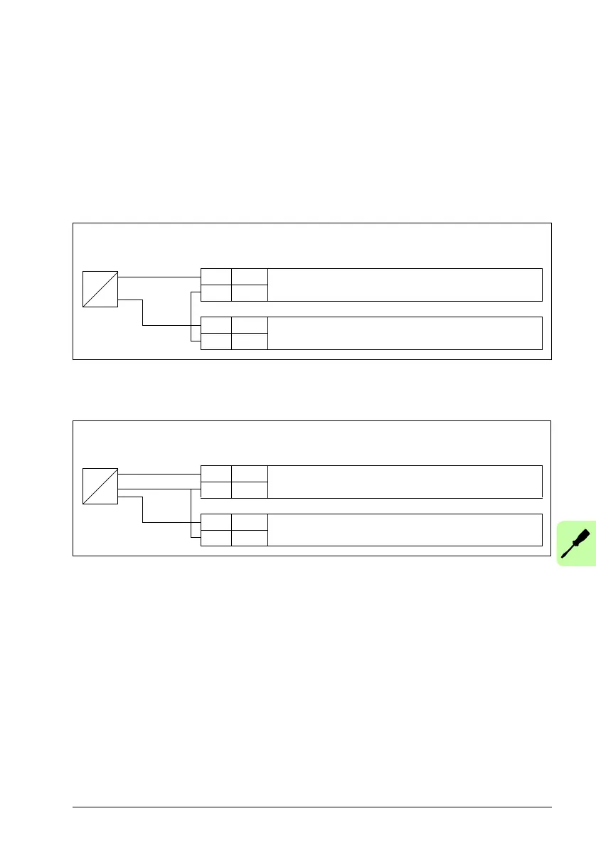
The figures below give examples of connections using a two-wire or three-wire
sensor/transmitter supplied by the drive auxiliary voltage output.
Note: Maximum capability of the auxiliary 24 V (200 mA) output must not be
exceeded.
Note: The sensor is supplied through its current output and the drive feeds the supply
voltage (+24 V). Thus the output signal must be 4…20 mA, not 0…20 mA.
Default I/O connection diagram
The default connection of the control signals depends on the application macro in
use, which is selected with parameter 9902 APPLIC MACRO.
The default macro is the ABB standard macro. It provides a general purpose I/O
configuration with three constant speeds. Parameter values are the default values
given in section Default values with different macros on page 180. For information on
other macros, see chapter Application macros on page 107.
X1A
5 AI2 Process actual value measurement or reference,
0(4)…20 mA, R
in
= 100 ohm
6GND
…
9 +24V Auxiliary voltage output, non-isolated,
+24VDC, max. 200mA
10 GND
4…20 mA
Two-wire sensor/transmitter
+
-
P
I
X1A
5 AI2 Process actual value measurement or reference,
0(4)…20 mA, R
in
= 100 ohm
6GND
…
9 +24V Auxiliary voltage output, non-isolated,
+24VDC, max. 200mA
10 GND
(0)4…20 mA
Three-wire sensor/transmitter
+
-
OUT
P
I

 Loading...


