42/24-10 EN Rev. 9 Chapter 7: Gas Analyzer Configuration 7-C-5
Setting Up System Modules
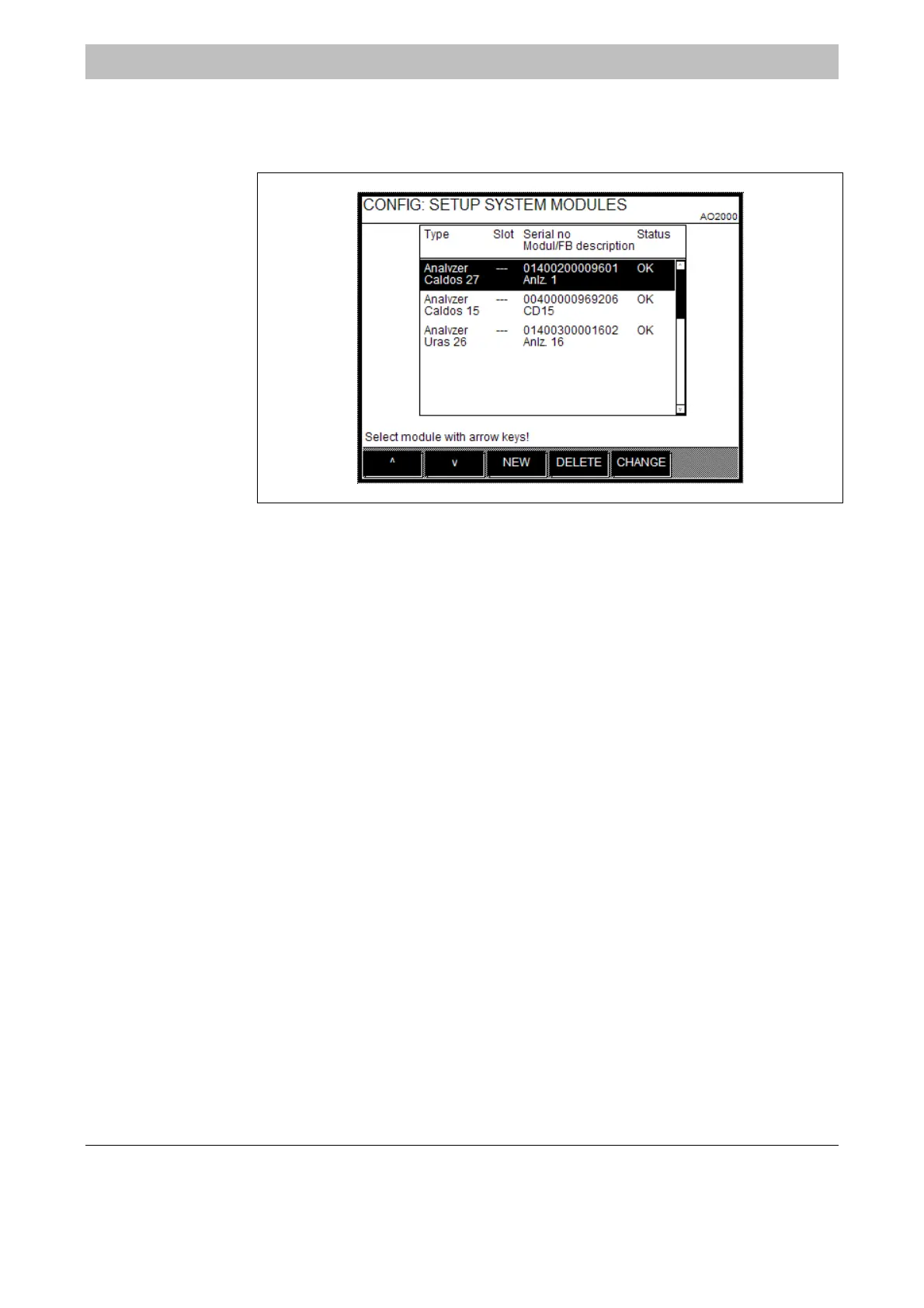
Menu Path MENU → Configure → System → Setup system modules
Figure 7-C-1
Setting Up
System Modules
Function If system modules are added to a gas analyzer, replaced (changed) or removed,
this modification must be configured in the software.
Definition System modules are
• Analyzer modules:
Uras26, Limas11, Magnos206, Magnos27, Caldos25, Caldos27, MultiFID14, ZO23
• I/O modules:
Profibus, Modbus, 2-way analog output, 4-way analog output, 4-way analog
input, digital I/O
• External I/O devices:
e.g. cooler I/O board.
Analyzer Modules
and
External I/O Devices
Analyzer modules and external I/O devices are connected to the system controller
via the system bus. They must be identified by their serial number (see below) in
order to be recognized by the gas analyzer.
I/O Modules I/O modules are plugged onto and directly connected with the system controller.
They have no serial numbers.
An I/O module is automatically recognized by the gas analyzer when it is added
for the first time or as replacement for an already existing I/O module.
Continued on next page

 Loading...


