42/24-10 EN Rev. 9 Chapter 3: Gas Line Connection 3-9
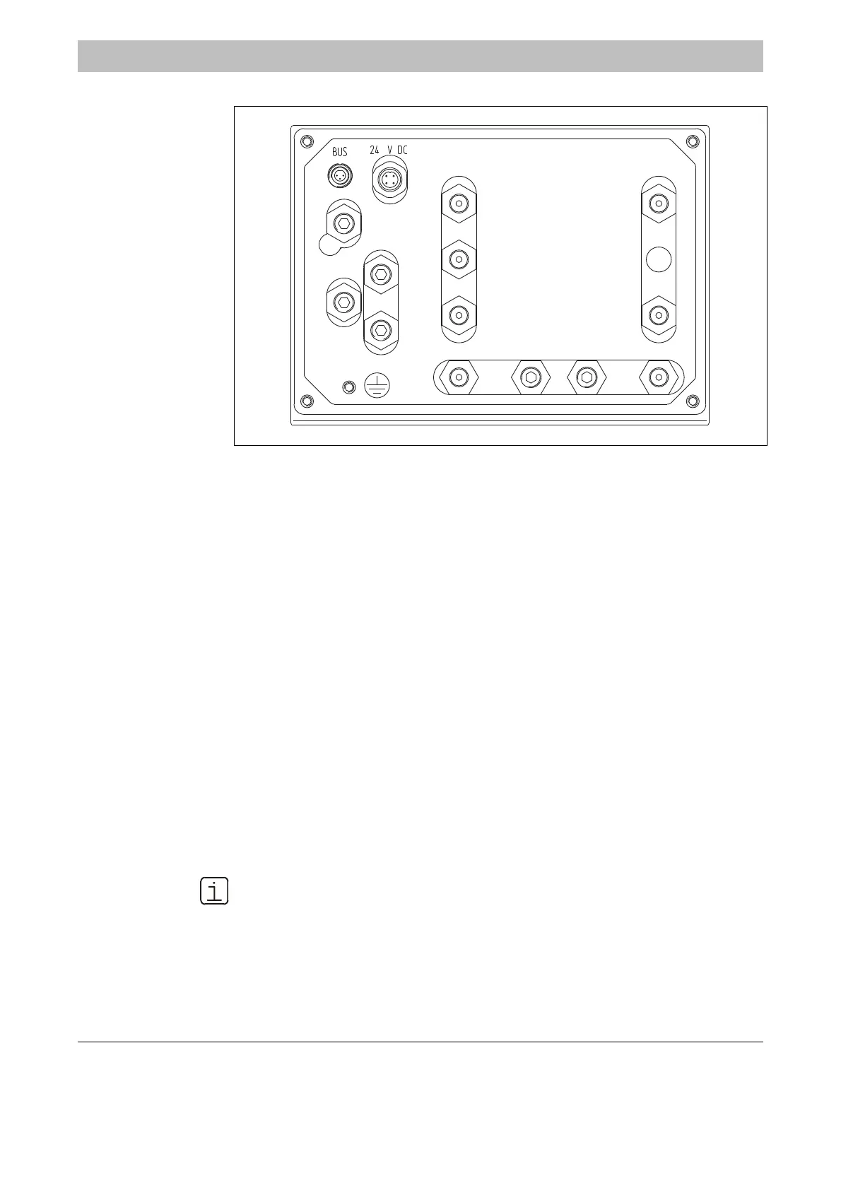
Uras26: Gas Connections
Figure 3-9
1
2
3
4
56
7
8
9
10
11
12
13
14
1 Pressure Sensor for External Pressure Measurement
1)
2 –
3 Sample Gas Inlet Gas Path 1
4 Sample Gas Outlet Gas Path 1
5 Purge Gas Inlet Housing
1)
6 Purge Gas Outlet Housing
1)
(also with Flow Sensor)
7 Sample Gas Inlet Gas Path 2
1)
(separate gas paths)
8 Sample Gas Outlet Gas Path 2
1)
(separate gas paths and gas paths in series)
9 Reference Gas Inlet Gas Path 1
1)
10 Reference Gas Outlet Gas Path 1
1)
Pneumatics Module
1)
:
11 Sample Gas Inlet Gas Path 1
12 End Point Gas Inlet (with 3 solenoids) or
Sample Gas Inlet Gas Path 2 (only with Flow Sensor)
13 Test Gas/Zero-Point Gas Inlet (with 1 or 3 solenoids) or
Sample Gas Outlet Gas Path 2 (only with Flow Sensor) >> 7
14 Sample Gas Outlet Gas Path 1 – Connect with Inlet 3
Gas Connections
1) Option
One of the several possible Uras26 connection arrangements is shown. The
actual connection arrangement of an analyzer module is found in the analyzer
data sheet for the delivered instrument.

 Loading...


