42/24-10 EN Rev. 9 Chapter 4: Electrical Connection 4-1
Chapter 4 Electrical Connection
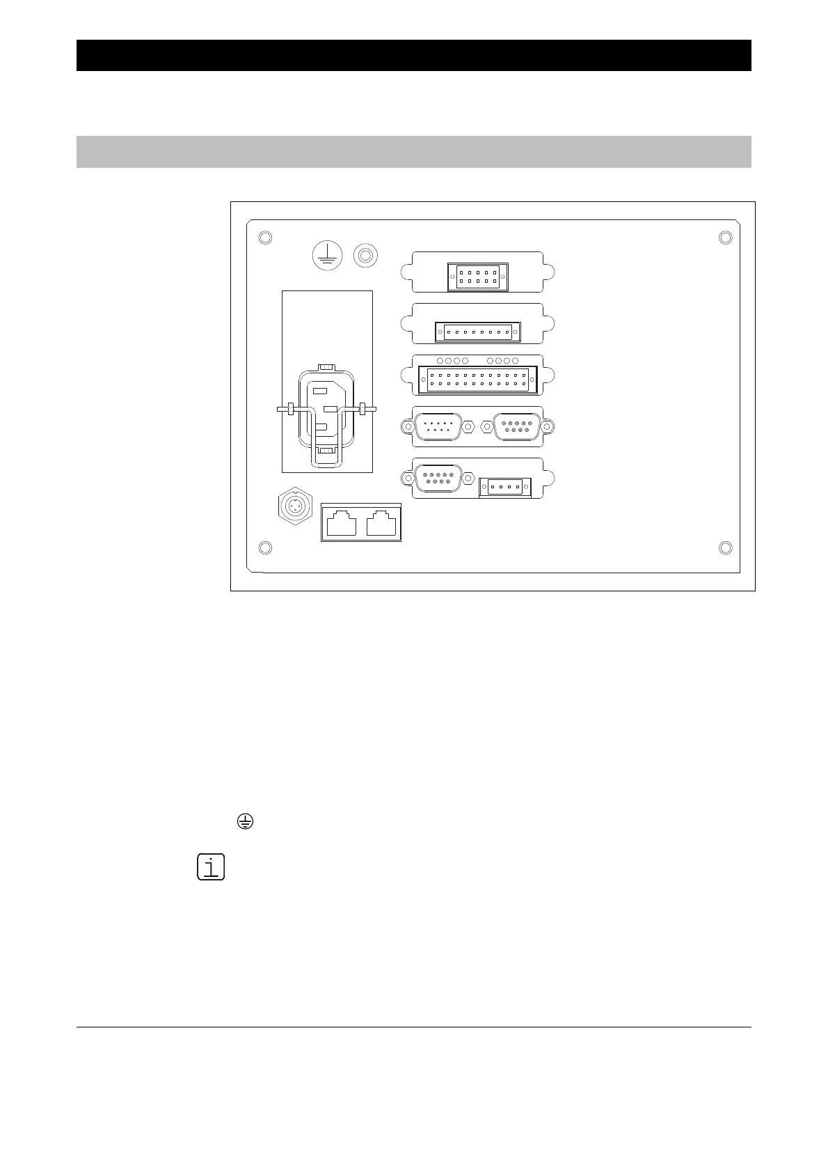
Electronics Module Connections
Figure 4-1
Electronics Module
Connections
1
6
1
6
1
6
-X29
-X27
-X25
-X26
-X24
-X22
-X20
-X28
-X23
-X21
-X07
-X01
-X08
-X09
For connection see
-X01 Power Supply Connection Page 4-18
-X07 System B
us Port Page 4-10
-X08, -X09 Ethernet 1
0/ 100/ 1000BASE-T Interface
I/O Modules (5 slots), Options:
– Profibus Module Page 4-2
– Modbus Module Page 4-3
– 2-Wa
y Analog Output Module Page 4-4
– 4-Wa
y Analog Output Module Page 4-5
– 4-Wa
y Analog Input Module Page 4-6
-X20 to -X29
– Digital I/O Module Page 4-7
Potential Compensation Connection Page 4-18
The connection drawing shows an example for the I/O modules equipment.

 Loading...


