4-16 Chapter 4: Electrical Connection 42/24-10 EN Rev. 9
Power Supply Line Connection to the Analyzer Module
• The following information and instructions should be followed when connecting
the 24-VDC power supply to an analyzer module that is not installed in the
central unit but in a separate system housing.
• Information in the sections “Power Supply Information”, page 1-7, and “Power
Supply”, page 1-8, should also be followed.
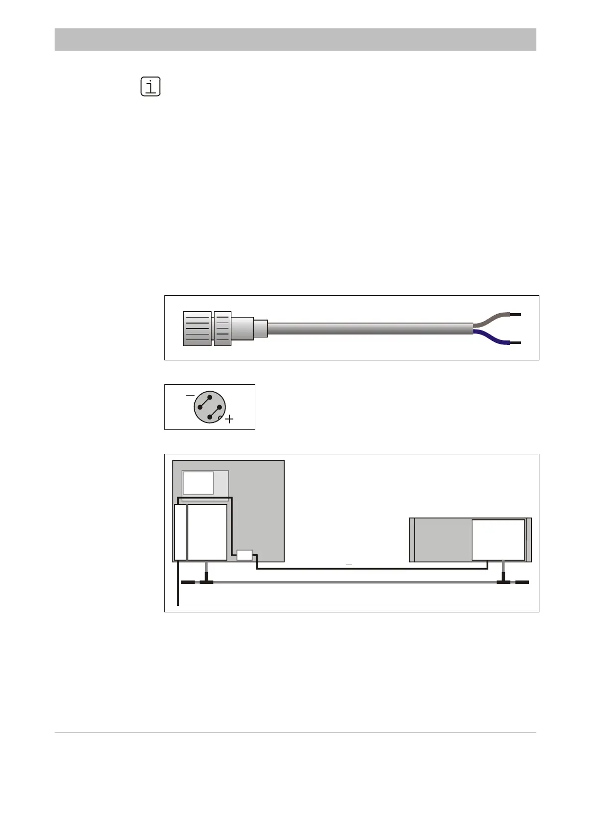
24-VDC Connecting
Cable
If an analyzer module is not installed in the central unit but in a separate system
housing a 5-meter (16.4-feet) long cable (2 x 0.5 mm
2
, see Figure 4-12) will be
supplied.
The receptacle on one cable end is designed to connect to the 24-VDC male plug
on the analyzer module or the I/O base module (see Figure 4-13).
The wires on the free end of the connecting cable are intended for connection to
• The power supply filter -Z01 in the central unit (for an example see Figure 4-14) or
• An external power supply
Figure 4-12
24-VDC Connecting
Cable
+
BU -
Figure 4-13
24-VDC Connection
1
4
2
3
The illustration shows the pin side of the analyzer module
plug and thus the solder side of the matching female jack.
Figure 4-14
Connecting 24-VDC
Power from the
Central Unit Power
Supply to a Separate
Analyzer Module
115
230 V A
-Z01
24 V DC
(0.5 mm , 5 m)
2
<
BUS
AM
P
S
CU
EM
AM Analyzer Module
CU Central Unit
EM Electronics Module
PS Power Supply
-Z01 Power Supply Filter
BUS System Bus
Continued on next page

 Loading...


