1-10 Chapter 1: Preparing the Installation 42/24-10 EN Rev. 9
Material Needed for Installation (not delivered)
Gas Connections • Threaded connections with 1/8 NPT threads and PTFE sealing tape
Flow Meter
• In the Caldos25 and Uras26 versions with flowing reference gas a flow meter
with a needle valve must be installed in the sample gas line and in the reference
gas line in order to adjust the flow rate in the two lines to the optimum value.
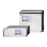
19-inch housing:
• 4 oval-head screws (Recommendation: M6; this depends on the cabinet/shelf
system).
• 1 pair of rails (Design depends on cabinet/shelf system).
Wall-mount housing:
Installation
• 4 M8 or M10 bolts.
• Selection of the required conductors depends on line length and planned
current load.
• Notes regarding conductor section for I/O module connection:
• The maximum capacity of terminals for stranded or solid conductors is 1 mm
2
(17 AWG).
• The stranded conductor may be tinned on the tip or twisted for simplified
connection.
• When using wire end ferrules the total section should not exceed 1 mm
2
,
i.e. the maximum stranded conductor section is 0.5 mm
2
. The Weidmüller
PZ 6/5 crimping tool must be used for crimping the ferrules.
• Maximum line length 1200 meters (3940 feet, transmission rate max. 19200 bit/s)
for RS485.
Signal Lines
• Maximum line length 15 meters (50 feet) for RS232.
Extension cable:
• Minimum conductor section 2.5 mm
2
.
• Maximum line length 30 m (100 feet).
Power supply:
Analyzer Module
24 VDC Supply
• If two analyzer modules are installed in the system housing, a power supply
outside the system housing must be provided. This power supply must equal
the rating of the AO2000 power supply (see page 1-8).
•
If the power cord supplied is not used, make your selection of a suitable cable
based on line length and planned current load.
Power Supply Line
• Provide a breaker in the power supply line or a switched receptacle to make
sure the gas analyzer can be completely separated from the power source.
 Loading...


