42/24-10 EN Rev. 9 Chapter 1: Preparing the Installation 1-11
List of Figures Related to Installation
Figure see Page
Dimensional diagrams
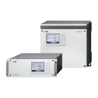
19-inch housing 2-4
Wall-mount housing 2-4
Gas connections
Magnos206 3-1
Magnos27 3-2
Magnos27 (sample cell direct connection) 3-3
Caldos25, Caldos27 3-4
Caldos25 (corrosive sample gas or flowing reference gas) 3-5
Limas11 (standard cell, quartz cell, cell with center connection) 3-6
Limas11 (quartz cell with PFA tubes) 3-7
Limas11 (safety cell) 3-8
Uras26 3-9
Electrical connections
Electronics module 4-1
Profibus module 4-2
Modbus module 4-3
2-way analog output module 4-4
4-way analog output module 4-5
4-way analog input module 4-6
Digital I/O module 4-7
System bus plug 4-11
Analyzer module 24-VDC connection 4-16
List of Figures Related
to Installation
Power supply connection 4-18
 Loading...


