132 Safety functions
SSE with speed limit activated SBC, SBC before STO
In these examples, the SBC function is activated at a user-defined speed limit and
drive STO function after a user-defined delay (negative SBC delay). The reason to
use a negative SBC delay (parameter SBC.12) is to have the mechanical brake
closed just before the drive STO circuit is opened.
With time monitoring
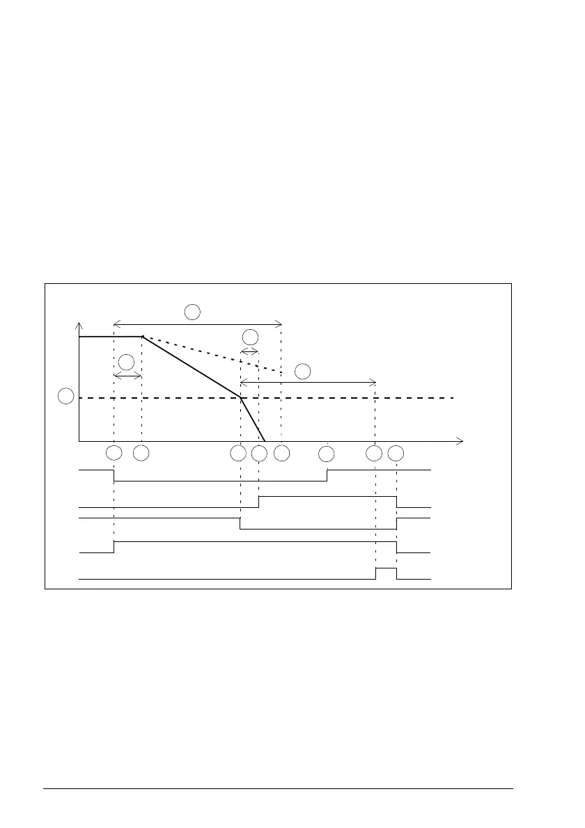
The operation of the SSE with speed limit activated SBC, SBC before STO and time
monitoring is described in the time diagrams and tables below. For configuration, see
section How to configure SSE with speed limit activated SBC, SBC before STO on
page 360.
With a safe speed estimate
A SBC speed (parameter SBC.15): Speed limit below which the FSO activates the SBC
function (brake).
B SSE delay for STO (parameter SSE.15): Time after which the FSO activates the STO
function regardless of the motor speed.
C SBC delay (parameter SBC.12): Time from the activation of the SBC function to the
moment when the FSO activates the drive STO function
.
D SBC time to zero (parameter SBC.13): Time from the SBC activation to the moment
when the safety function is completed and the SSE completed indication (parameter
SSE.22) goes on. The acknowledgment becomes allowed. You must set this to the
estimated time in which the motor brakes to a stop from the maximum speed.
E Response time (depends on system configuration, see page 532)
Drive STO state
& indication
SSE request
Motor speed
Time
SSE state &
indication
1
7
2
SBC output
3
A
E
SSE completed
indication
B
SSE.15
3b
C
SBC.12
D
SBC.13
4 6
5
- -> Safe torque off (STO)

 Loading...


