Planning for installation 289
Note: You can use calculation software to assist in selecting the appropriate
architecture that will meet the safety integrity requirements for a particular application.
Use, for example, ABB’s Functional safety design tool, see Functional safety design
tool user’s manual (3AXD10000102417 [English]).
STO cable and data cable between FSO module and drive
For the specifications, see STO cable and data cable between FSO module and drive
on page 517.
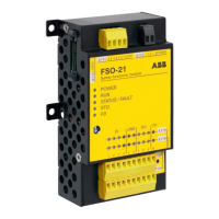
Power supply connection/cables
The system must be protected against over-voltage and over-current.
The length of the cabling between the FSO and its power supply must be
three meters or shorter, or a sufficiently low interference level must be otherwise
guaranteed.
Note: The 24 V DC power supply should be equipped with a supply disconnecting
device to enable an easy start-up of the FSO module.
Note: The FSO module power input (X112) is protected against over-voltage, under-
voltage and over-current, and it has a reverse polarity protection. FSO module enters
Fail-safe mode if any of these protections trip. The module enters Fail-safe mode also
if output voltages of the internal power supply are outside specified limits due to
supply input over-voltage.
Note: If you de-energize the FSO module, you cannot operate the drive.
Power supply for the FSE module and safety encoders
You have to use the same power supply for the FSE and FSO modules. The length of
the cabling between the FSE and the power supply must be no more than three
meters, or a sufficiently low interference level must otherwise be guaranteed. For
more information, see FSE-31 pulse encoder interface module user's manual
(3AXD50000016597 [English]).
If an internal safety encoder failure occurs, the safety encoder goes into the Safe
state. To recover from these situations, you have to be able to reboot the safety
encoder (for example, by switching the power off and on).
If FSE module goes to power-down mode while FSO is in power-on mode, FSO will
activate STO and indicate Fail-safe state.
Ensuring the EMC compatibility
The system must only be used in the EMC environment it is designed for, or
necessary mitigations must be applied.

 Loading...