354 Configuration
How to configure SSE with time monitoring
For more information on the SSE function with time monitoring, see page 116.
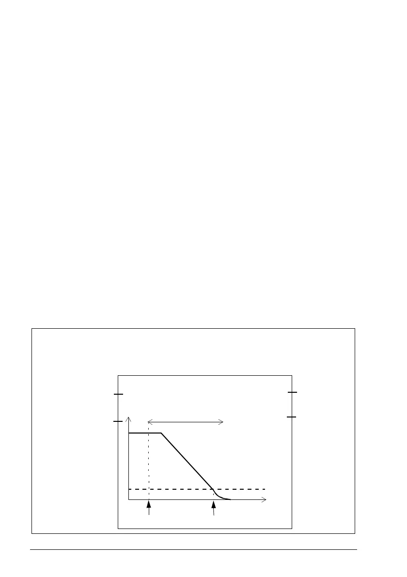
Example: The figure below shows an example of the SSE function with time
monitoring set-up:
• SAR0 emergency ramp (200.102 SAR0 ramp time to zero, always with the SSE
function - see section Configuring SAR on page 361)
• SSE with time monitored ramp (SSE.13 SSE function = Emergency ramp,
SSE.14 SSE monitoring method = Time)
• delay for STO activation after SSE request: 2000 ms
(SSE.15 SSE delay for STO = 2000 ms)
• automatic acknowledgement (STO.02 STO acknowledgement = Automatic)
• redundant emergency stop button connected to input
(SSE.11 SSE input A = DI X113:1 & X114:1)
• single output connected (SSE.21 SSE output = DO X113:9)
• zero speed limit where SSE function is completed and drive STO activated is
90 rpm (FSOGEN.51 Zero speed without encoder = 90 rpm)
(when an encoder is used: FSOGEN.52 Zero speed with encoder = 90 rpm)
• delay for activating the drive STO after the speed limit has been reached: 0 ms
(SSE.16 SSE ramp zero speed delay for STO = 0ms)
• speed limit activated brake not in use
(SBC.15 SSE/SS1 SBC speed = 0rpm)
• See also section Configuring mute times on page 393.
SSE.14 = Time
SSE.15 = 2000 ms
Time
Speed
SSE activated
Inputs
Outputs
STO activated
FSOGEN.51
= 90 rpm
SSE.13 = Emergency ramp
STO.02 = Automatic
SSE.11
= DI X113:1 & X114:1
SSE.12
= None
SSE.21
= DO X113:9
SSE.22
= None
SBC.15
= 0 rpm
SSE.16 = 0 ms

 Loading...


