Overview 41
FSO diagnostics
The FSO module performs extensive auto diagnostics tests during the runtime
operation on FSO internal parts as well as the communication and STO connection
between the FSO and the drive. The FSO goes into the Fail-safe mode if it detects a
fault.
• The communication between the FSO and the drive is diagnosed continuously.
• The STO connection between the FSO and the drive STO connector is diagnosed
during the power-up and periodically during the runtime.
If an FSO redundant I/O failure occurs, FSO module activates (or keeps active) the
safety function that has been configured to the I/O. For all other I/O or safety fieldbus
failures, the FSO module activates the SSE function. Also, the overtemperature fault
of the FSO module activates the SSE function (for more information, see section
Configuring SSE on page 351). In other internal failure situations, the FSO module
activates the STO function.
I/O
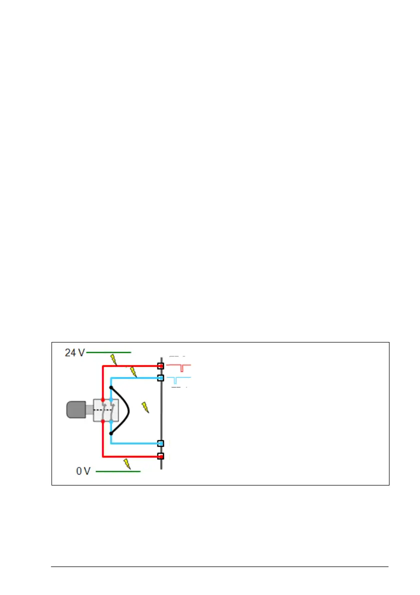
The FSO module supports input and output redundancy.
The FSO module provides an option for applying diagnostic pulsing for its inputs and
outputs. When applied, the pulsing enables the FSO diagnostics to detect cable
failures as follows:
• Inputs: Open-circuiting and short-circuiting failures are detected with diagnostic
pulsing. The failures that short-circuit the sensor are detected upon input
activation when redundant connection is used.
Note: If only one of the redundant inputs is activated upon a safety function request,
the FSO module activates the safety function in which the input is configured but it
cannot be acknowledged before the failure has been repaired. To acknowledge the
safety function, you must set both input channels down and up at the same time or,
switch the power off and on.
1. Failure is detected
2. Failure is detected upon
input activation when
redundancy is used
TP2
DI1
DI2
TP1
Diagnostic pulse 2
Diagnostic pulse 1
Digital input 1
Digital input 2
1
1
2
1

 Loading...


