 Loading...
Do you have a question about the ABB FSO-21 and is the answer not in the manual?
| Brand | ABB |
|---|---|
| Model | FSO-21 |
| Category | Control Unit |
| Language | English |
Electrical safety precautions for personnel working on drives, motor cables, or motors.
Details safety functions supported by FSO-21 module per EN/IEC 61800-5-2.
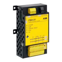
FSO-21 adds safety functionality to drives, supporting PROFIsafe and safety encoders.
Activates drive STO function to bring machine to a no-torque state by stopping motor.
Safely stops motor by ramping down speed to zero, monitored by time or ramp method.
Stops motor safely by coasting or ramping down, similar to STO or SS1.
Provides safe output for external safety brakes, always combined with drive STO.
Prevents motor exceeding user-defined speed limits; activates SSE if trip limit is reached.
Allows scaling of SLS limits via safety PLC using PROFIsafe.
Protects machine from high speeds/frequencies; can be permanently on or off.
Prevents machine from starting unexpectedly by activating drive STO.
Provides safe output signal for motor speed within user-defined limits.
Monitors correct motor rotation; activates SSE if forbidden direction is exceeded.
Provides safe deceleration ramp monitoring for other safety functions.
Overview of safety system configuration process: risk assessment, requirements, design, validation.
Steps for setting FSO parameters using Drive composer pro PC tool.
Configuring SBC function with STO, SSE, SS1, considering delays and speed limits.
Setting SBC usage, delay, and speed limit parameters for SBC in STO function.
Setting FSO parameters for STO function: input, acknowledgement, output configurations.
Setting SS1 parameters for time monitoring: activation, delays, acknowledgement, outputs.
Setting SS1 parameters for ramp monitoring: activation, SAR1, acknowledgement, outputs.
Configuring SSE with immediate STO: activation, acknowledgement, and output settings.
Configuring SSE with ramp monitoring: activation, SAR0, acknowledgement, outputs.
Setting FSO parameters for SLS functions (SLS1-4, Variable SLS): limits and trip limits.
Configuring SLSn with time monitoring: activation, delay, acknowledgement, outputs.
Configuring Variable SLS with time monitoring: activation, acknowledgement, delays, outputs.
Configuring SMS function (version 1 or 2) for protection against high speeds/frequencies.
Configuring POUS function to prevent unexpected start-up: activation, acknowledgement, inputs, delay, outputs.
Configuring SSM function for monitoring motor speed between user-defined limits.
Configuring SDI function to monitor correct motor rotation, requiring an encoder.
Validates SBC function, ensuring correct wiring and configuration for delayed brake and speed limit activated brake.
Validates SSE function: immediate STO, emergency ramp with safe speed estimate or encoder.
Validates SS1 function: inputs, SAR1/time monitoring settings, acknowledgement, indications.
Validates SLS functions (SLS1-4): inputs, functionality, acknowledgement, indications for ramp/time monitoring.
Validates variable SLS function: PLC scaling, inputs, acknowledgement, outputs.
Validates SMS functions (version 1 and 2): activation, limits, SSE function configuration.
Validates POUS function: inputs, outputs, activation, acknowledgement, functionality.
Validates SSM functions (SSM1-4): inputs, outputs, activation, limits.
Validates SDI functions: inputs, configuration, tolerance limits, acknowledgement for ramp/time monitoring.
Instructions for replacing FSO/FSE modules, control units, or FB modules, ensuring safety during process.
Resets FSO to factory settings; requires reconfiguration. Backup safety file before reset.
Categorizes safety functions into Stopping and Speed-related, listing specific functions.
Prevention of unexpected start-up function.
Determines SIL/PL capability by adding failure rates of components.
Subsystem for PROFIsafe connection reliability, handled by FSO module via FENA/FPNO.
Lists FSO-21 safety data related to IEC 61508, EN ISO 13849-1, IEC 61511, EN IEC 62061.