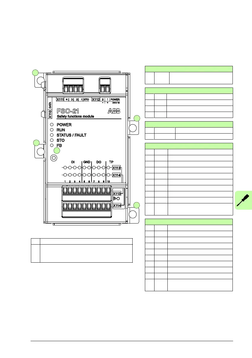
X110:
DATA Data connection to the drive
control unit
X111:
1STOSTO 24V
2 STO STO ground
3 STO STO1LO drive internal signal
4 STO STO2LO drive internal signal
X112:
1POWER24V
2POWER0V
X113:
1 DI Channel 1 digital input 1
2 DI Channel 1 digital input 2
3 DI Channel 1 digital input 3
4 DI Channel 1 digital input 4
5 GND Signal ground
6 GND Signal ground
7 DO Channel 1 digital output 1
8 DO Channel 1 digital output 2
9 DO Channel 1 digital output 3
10 TP Channel 1 diagnostic pulse
out
X114:
1 DI Channel 2 digital input 1
2 DI Channel 2 digital input 2
3 DI Channel 2 digital input 3
4 DI Channel 2 digital input 4
5 GND Signal ground
6 GND Signal ground
7 DO Channel 2 digital output 1
8 DO Channel 2 digital output 2
9 DO Channel 2 digital output 3
10 TP Channel 2 diagnostic pulse
out
A Electronics grounding screw
B Enclosure grounding screw, at any of the
mounting points, depending on the
installation type

 Loading...


