390 Configuration
How to configure SDI with time monitoring
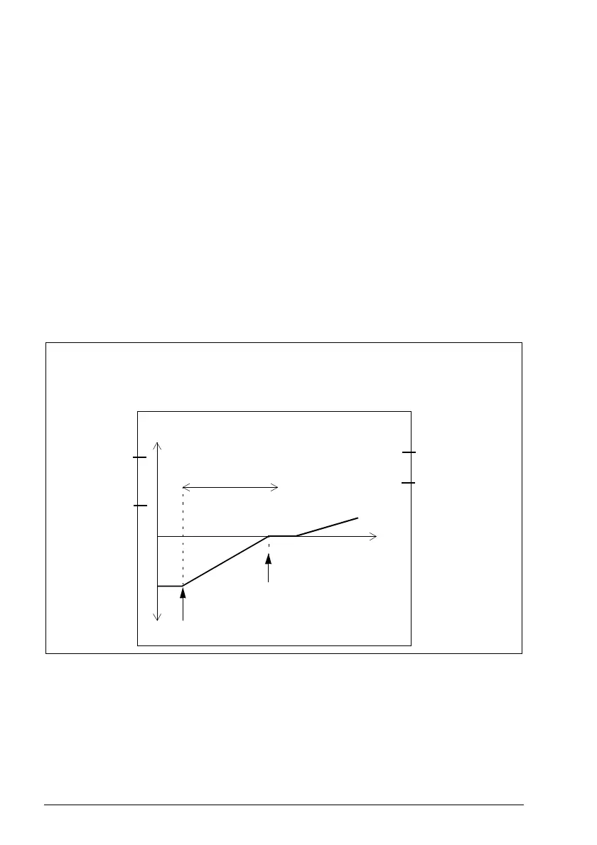
Example: The figure below shows an example of an SDI positive function with time
monitoring set-up:
• Version 1 of SDI functions activated (SDI.01 SDI version = Version 1)
• SDI positive function activated (SDI.02 SDI positive activity = Enabled)
• time monitored ramp (SDI.10 SDI activation monitoring method = Time)
• deceleration ramp according to drive parameters (always with time monitoring)
• SDI activation delay 2000 ms (SDI.12 SDI delay = 2000 ms)
• SDI tolerance into the forbidden direction 2 degrees
(SDI.14 SDI tolerance limit degree = 2deg)
• automatic acknowledgement (SDI.13 SDI acknowledgement = Automatic)
• redundant activation button connected to input
(SDI.21 SDI positive input A = DI X113:2 & X114:2)
• single output connected (SDI.23 SDI positive output A = DO X114:7).
SDI.21
= DI X113:2 &
X114:2
SDI.22
= None
SDI.23
= DO X114:7
SDI.24
= None
SDI.10 = Time
SDI.13 = Automatic
SDI.12 = 2000 ms
SDI positive
Time
Speed
Inputs
Outputs
SDI activated
SDI monitoring started
SDI.01 = Version 1
SDI.14 = 2 deg
(not shown in the
figure)

 Loading...


