376 Configuration
Configuring POUS
How to configure POUS
To configure the POUS function, set the FSO parameters listed below to appropriate
values using the Drive composer pro PC tool. See parameter group POUS on
page 415.
For more information on the POUS function, see page 180.
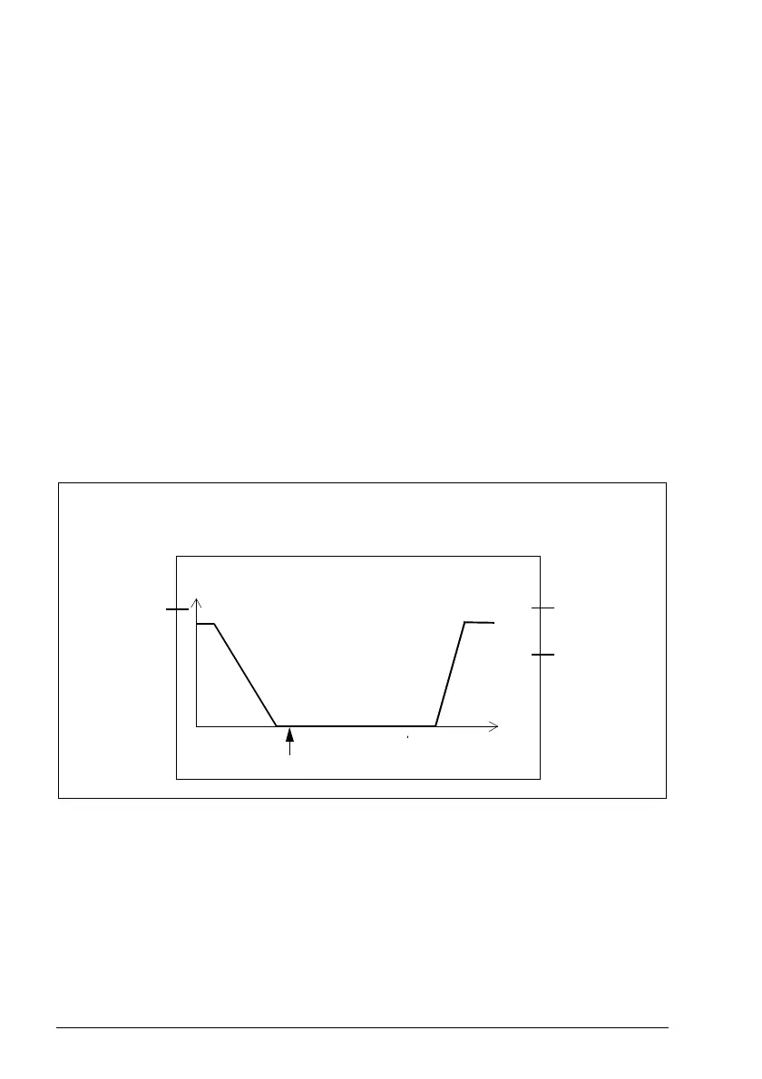
Example: The figure below shows an example of the POUS function set-up:
• POUS function activated (POUS.01 POUS activity and version = Version 1)
• automatic acknowledgement (POUS.02 POUS acknowledgement = Automatic)
• redundant POUS switch connected to inputs X113:1 and DIX114:1
(POUS.11 POUS input = DI X113:1 & X114:1)
• delay for POUS complete indication: 0 (POUS.13 POUS delay for completion = 0
ms)
• POUS completed output (for example, an indication lamp) connected to single
output: X114:9 (POUS.22 POUS completed output = DO X114:9).
How to configure SLS function behavior when drive
modulation is lost
When it is critical for the process that the drive must be able to indicate safely if the
drive modulation is lost during SLS deceleration, user must configure this behavior
separately for the SLS function. Once the configuration for the modoff behavior is
made, it is the same for SLS 1…SLS 4 functions and for variable SLS function.
POUS.21
= None
POUS.22
= DO X114:9
Speed
POUS.11
= DI X113:1 &
X114:1
Time
POUS.02 = Automatic
Input
Outputs
POUS activated
POUS.13 = 0 ms
POUS.01 = Version 1

 Loading...


