38 Overview
Layout
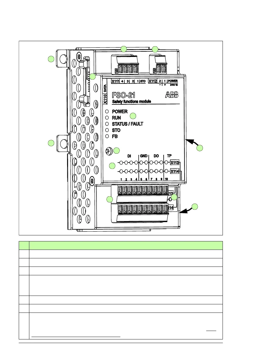
No Description
1 24 V DC input connection
2 Safe torque off (STO) connection
3 Data connection
4,
4b
Mounting for drives with ZCU-12 control unit shown. Two mounting points on each side.
The screw fixed at 4b also grounds the enclosure of the FSO. Mounting points for drives
with other control units may vary.
5 FSO grounding screw, grounds the electronics
6 FSO status LEDs, see section Status LEDs on page 489.
7 Input / output status LEDs, one for each I/O connector. The LEDs are in two rows above
the corresponding two rows of I/O connectors. The LED is lit if the state of the
corresponding I/O is ON (24 V in the input or output). The data shown by LEDs is only
indicative and cannot be considered safe.

 Loading...


