Safety functions 173
Variable SLS with time monitoring
In Variable SLS with time monitoring, the ramp according to which the drive
decelerates the motor to different speeds is monitored using the time monitoring
method. Drive parameters define the deceleration ramp. If the motor speed is
accelerated, drive parameters define the acceleration ramp and it is not monitored.
For configuration, see section How to configure Variable SLS with time monitoring on
page 366.
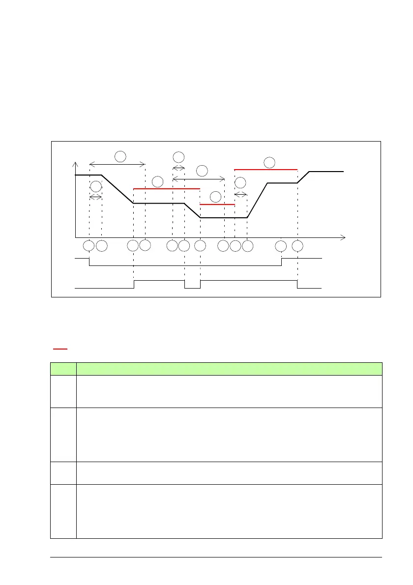
A Variable SLS trip limits (parameter SLSx.43 and the scaling values set in the safety PLC)
B SLS time delay (parameter SLSx.04): Delay for forcing to start SLS monitoring.
C Response time (depends on system configuration, see page 532)
Variable SLS trip limit (A)
Step Description
1 The Variable SLS request is received from the safety PLC (for example, 70%). The
FSO sends a request to the drive to ramp down the motor speed to the new SLS speed
limit. The FSO start a counter for the SLS time delay (B).
2 After time C has elapsed, the drive starts to ramp down the motor speed. The drive
(parameter 23.13 or 23.15) defines the deceleration ramp.
The FSO starts the SLS monitoring when the motor speed is in the middle of the new
SLS limit and the SLS trip limit (see also section How to configure mute time for
monitoring start on page 399).
3 The new motor speed has been reached. The Variable SLS active indication
(parameter SLSx.51) goes on.
4 The FSO starts the SLS monitoring at the latest here, that is, after the SLS time delay
(B) has elapsed.
Note: If the motor speed is above the SLS trip limit after the SLS time delay (B) has
elapsed, the FSO module activates the SSE function. For more information, see
section SLS with time monitoring and speed above monitored speed on page 143.
varSLS status
& indication
C
2 5
varSLS request
4
B
Motor speed
Time
6 7 8
9 10
11
12
B
A
C
C
A
A
31

 Loading...


