Rockwell Automation Publication 1756-UM540E-EN-P - December 2017 113
Install ControlLogix Analog I/O Modules Chapter 6
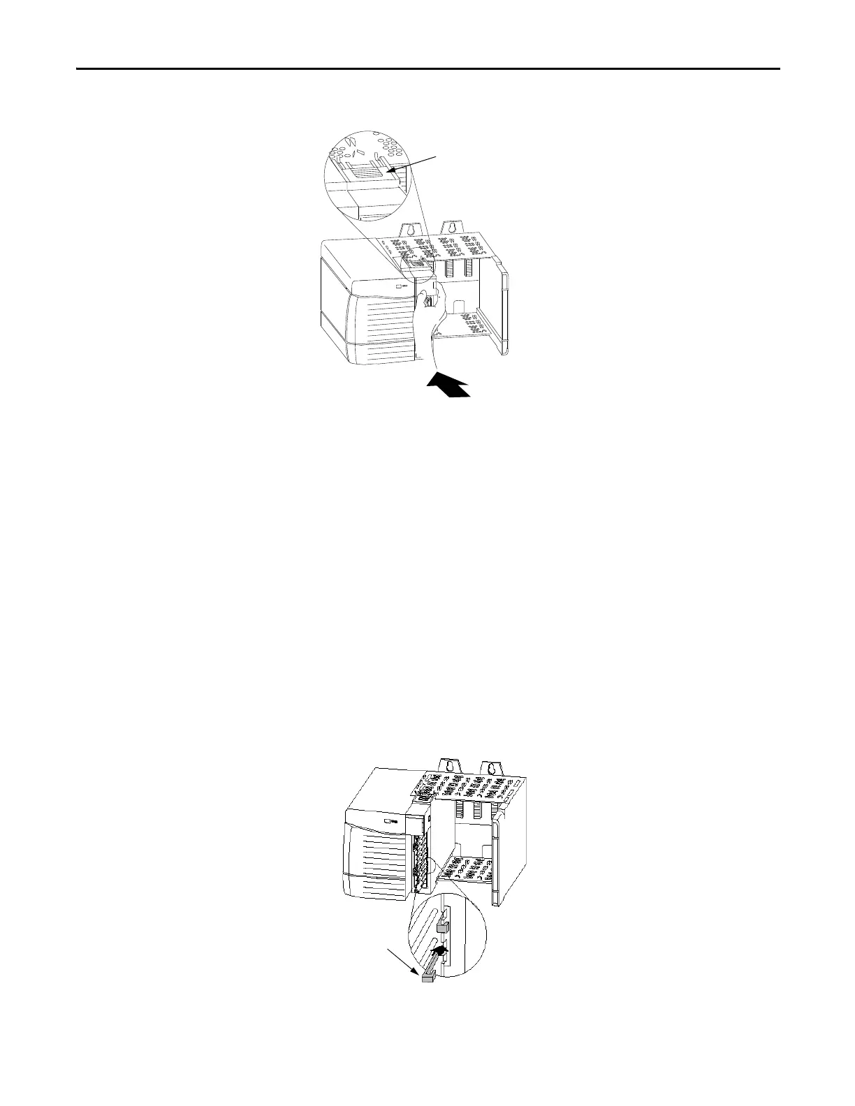
2. Slide the module into the chassis until the module locking tab clicks.
Key the Removable
Terminal Block
Key the removable terminal block (RTB) to prevent inadvertently connecting the
wrong wiring in the RTB to your module. Wedge- and U-shaped bands are
manually inserted into the RTB and module. This process hinders a wired RTB
from being accidentally inserted into a module that does not match the
positioning of the respective tabs.
Key positions on the module that correspond to unkeyed positions on the RTB.
For example, if you place a U-shaped keying band in slot 4 on the module, you
cannot place a wedge-shaped tab in slot 4 on the RTB or your RTB does not
mount on the module. We recommend that you use a unique keying pattern for
each slot in the chassis.
Complete the following steps to key the RTB.
1. Insert the U-shaped band with the long side near the terminals.
2. Push the band onto the module until it snaps into place.
3. Key the RTB in positions that correspond to unkeyed module positions.
U-shaped Keying
Band
20850-M
 Loading...


