EasyManua.ls Logo

Allen-Bradley 1756-IR12 User Manual

Allen-Bradley 1756-IR12
226 pages
To Next Page IconTo Next Page
To Previous Page IconTo Previous Page
Page #212 background imageLoading...
Page #212 background image
212 Rockwell Automation Publication 1756-UM540E-EN-P - December 2017
Appendix A Analog I/O Module Tag Definitions
Array Data Structures
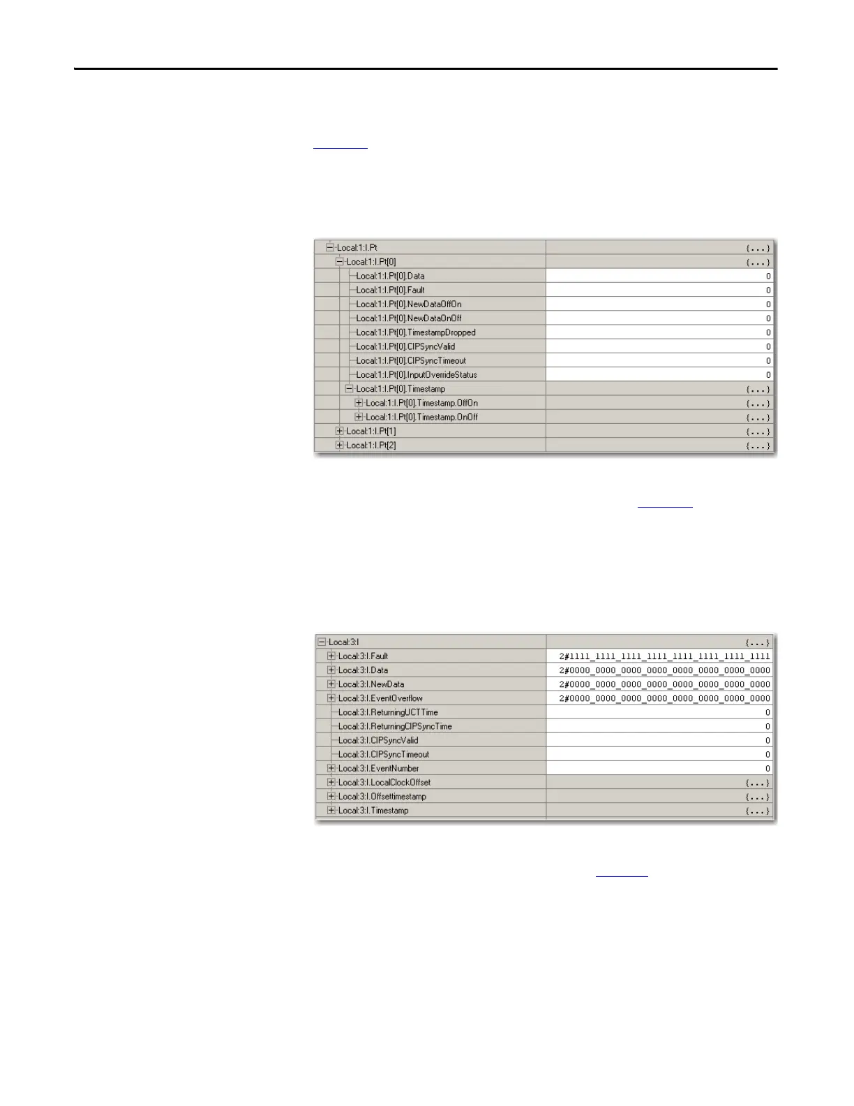
Fast digital I/O modules use an array data structure. In this type of structure, all
the tags for a particular point are organized under that point. For example, in
Figure 33
, all of the tags that appear under point 0 also appear under points 1…15
for the input module in slot 1. With this structure, you can copy or access all of
the data for a particular point by simply referencing or copying the point or alias
for the point, such as Pt[3] or PressureValveTank3.
Figure 33 - Array Data Structure
Other digital I/O modules use a flat data structure. In this type of structure, only
one instance of a tag exists for a module. For example, in Figure 34
, only one
instance of each tag appears under the input module in slot 3. To reference or
copy data for an individual point, you specify the tag name followed by a bit
number, such as Data.0 or EventOverflow.3. Unlike an array structure where all
the data for a point can be accessed via a single tag reference, a flat structure
requires multiple tag references to access all the data for a point.
Figure 34 - Flat Data Structure
The 1756-OF8I module uses either type of data structure depending on how you
configure the module. For more information, see page 204
.

Table of Contents

Questions and Answers:

Allen-Bradley 1756-IR12 Specifications

General IconGeneral
BrandAllen-Bradley
Model1756-IR12
CategoryI/O Systems
LanguageEnglish

Summary

Chapter 1 Analog I/O Module Operation in the ControlLogix System

Configure a Module

Describes how to configure I/O modules using the Logix Designer application.

Input Module Operation

Explains how ControlLogix analog input modules broadcast data to their backplane.

Output Module Operation

Explains how RPI defines when a controller sends data to analog output modules.

Chapter 2 Analog I/O Module Features

Calibration

Details the methods for calibrating ControlLogix analog modules.

Chapter 3 1756-IF8I Isolated Analog Input Module

1756-IF8I Module Features

Lists the features of the 1756-IF8I Isolated Analog Input Module.

Fault and Status Reporting

Details how the module multicasts fault and status data via module tags.

Chapter 4 Temperature-sensing Analog Modules

Common Module Features

Lists common features available across temperature-sensing analog modules.

Process Alarms

Alerts when the module exceeds configured high or low limits for each channel.

Rate Alarm

Triggers if the rate of change between input samples exceeds a specified trigger point.

Cold Junction Compensation

Explains the need to compensate for thermoelectric effects in thermocouple measurements.

Chapter 5 1756-OF8I Isolated Analog Output Module

1756-OF8I Module Features

Lists the features of the 1756-OF8I Isolated Analog Output Module.

Redundant Owners

Allows a single controller to use redundant adapters or two controllers to coordinate output.

Configure the Output Module

Steps to configure output modules for redundant owner applications.

Troubleshooting

Provides guidance for troubleshooting common issues with output modules.

Chapter 6 Install ControlLogix Analog I/O Modules

Install the I/O Module

Describes how to install or remove a module while chassis power is applied.

Chapter 7 Configure ControlLogix Analog I/O Modules

Create a New Module

Steps to create a module in a Logix Designer application project.

Edit the Configuration

Explains how to use tabs in the New Module dialog box to edit configuration.

Configuration Tab

Details fields specific to module type for tasks like selecting I/O type and range.

Calibration Tab

Allows recalibration of the module to correct hardware inaccuracies.

Alarm Configuration Tab

Details fields specific to module type for disabling alarms and setting parameters.

Chapter 8 Calibrate the ControlLogix Analog I/O Modules

Calibrate Via Profile or Ladder

Describes calibrating modules online via software using Ladder Logic or Module Profile.

Calibrate the Input Modules

Details the multi-step process for calibrating input modules.

Calibrate the 1756-IF8I Module For Voltage Input Type

Provides steps for calibrating the 1756-IF8I module using voltage inputs.

Calibrate the Temperature-sensing Modules

Guides calibration for 1756-IRT8I, 1756-IR12, and 1756-IT16 modules.

Calibrate the Module for an RTD Input Type

Explains the process for calibrating modules with RTD input types using precision resistors.

Calibrate the Module for a Thermocouple Input Type

Provides steps for calibrating modules with thermocouple input types.

Calibrate the Output Module

Guides calibration for the 1756-OF8I module with current or voltage outputs.

Calibrate the 1756-OF8I Module for a Current Output Type

Details steps for calibrating the 1756-OF8I module for current output.

Chapter 9 Troubleshoot Your Module

Status Indicators for the 1756-IF8I Module

Explains the status indicators for the 1756-IF8I module.

Status Indicators for the 1756-IRT8I Module

Explains the status indicators for the 1756-IRT8I module.

Status Indicators for the 1756-IR12 Module

Explains the status indicators for the 1756-IR12 module.

Status Indicators for the 1756-IT16 Module

Explains the status indicators for the 1756-IT16 module.

Status Indicators for the 1756-OF8I Module

Explains the status indicators for the 1756-OF8I module.

Related product manuals