116 Rockwell Automation Publication 1756-UM540E-EN-P - December 2017
Chapter 6 Install ControlLogix Analog I/O Modules
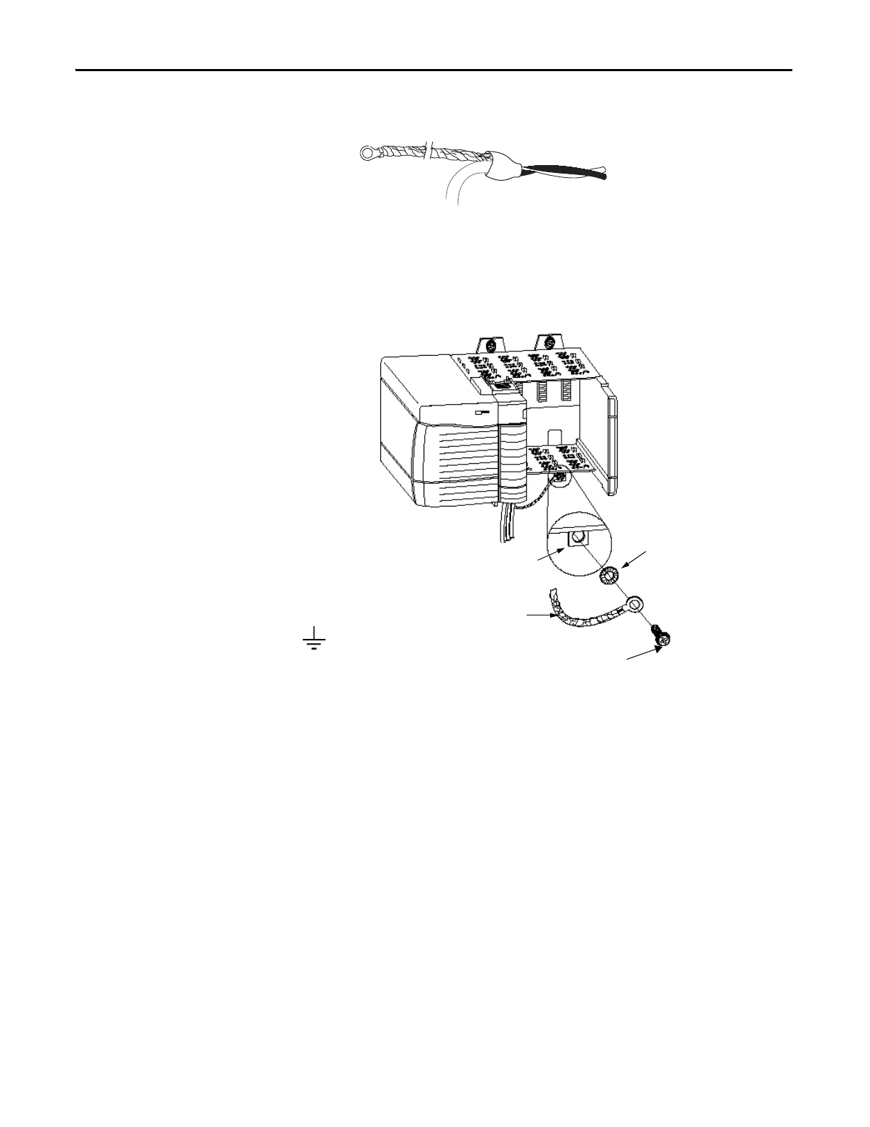
4. Attach a ground lug and apply heat shrink tubing to the exit area.
5. Connect the drain wire to a chassis mounting tab.
Use any chassis mounting tab that is designated as a functional signal
ground. The functional earth ground symbol appears near the tab.
6. When the drain wire is grounded, connect the insulated wires to the field-
side.
Connect the Ungrounded End of the Cable
1. Cut the foil shield and drain wire back to the cable casing and apply shrink
wrap.
2. Connect the insulated wires to the RTB.
Chassis Mounting Tab
Drain Wire with Ground Lug
4 m or 5 m (#10 or #12)
Star Washer
4 m or 5 m (#10 or #12) Star Washer Phillips Screw
and Star Washer (or SEM Screw)
20918-M
Functional Earth
Ground Symbol
 Loading...


