EasyManuals Logo
Home>Allen-Bradley>I/O Systems>1756-IR12

Allen-Bradley 1756-IR12 User Manual

Allen-Bradley 1756-IR12
226 pages
To Next Page IconTo Next Page
To Previous Page IconTo Previous Page
Page #119 background imageLoading...
Page #119 background image
Rockwell Automation Publication 1756-UM540E-EN-P - December 2017 119
Install ControlLogix Analog I/O Modules Chapter 6
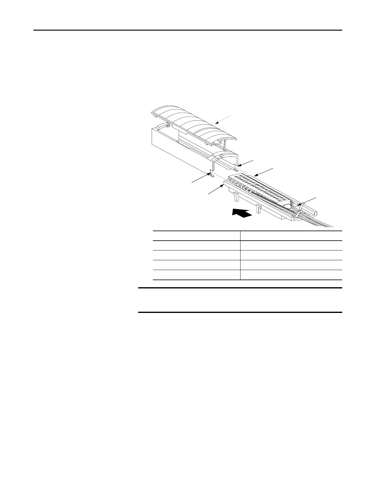
Assemble the RTB and the
Housing
Removable housing covers the wired RTB to protect wiring connections when
the RTB is seated on the module.
1. Align the grooves at the bottom of each side of the housing with the side
edges of the RTB.
2. Slide the RTB into the housing until it snaps into place.
1
4
3
2
3
2
20858-M
Item Description
1Housing cover
2Groove
3 Side edge of RTB
4 Strain relief area
IMPORTANT
If additional wire routing space is required for your application, use the
extended-depth housing, catalog number 1756-TBE.

Table of Contents

Questions and Answers:

Question and Answer IconNeed help?

Do you have a question about the Allen-Bradley 1756-IR12 and is the answer not in the manual?

Allen-Bradley 1756-IR12 Specifications

General IconGeneral
BrandAllen-Bradley
Model1756-IR12
CategoryI/O Systems
LanguageEnglish

Related product manuals