EasyManua.ls Logo

Allen-Bradley 1756-IR12 User Manual

Allen-Bradley 1756-IR12
226 pages
To Next Page IconTo Next Page
To Previous Page IconTo Previous Page
Page #88 background imageLoading...
Page #88 background image
88 Rockwell Automation Publication 1756-UM540E-EN-P - December 2017
Chapter 4 Temperature-sensing Analog Modules
Fault and Status Reporting
The module multicasts fault and status data with channel data to the owner and
listening controllers. The data is returned via module tags that you can monitor
in your Logix Designer application.
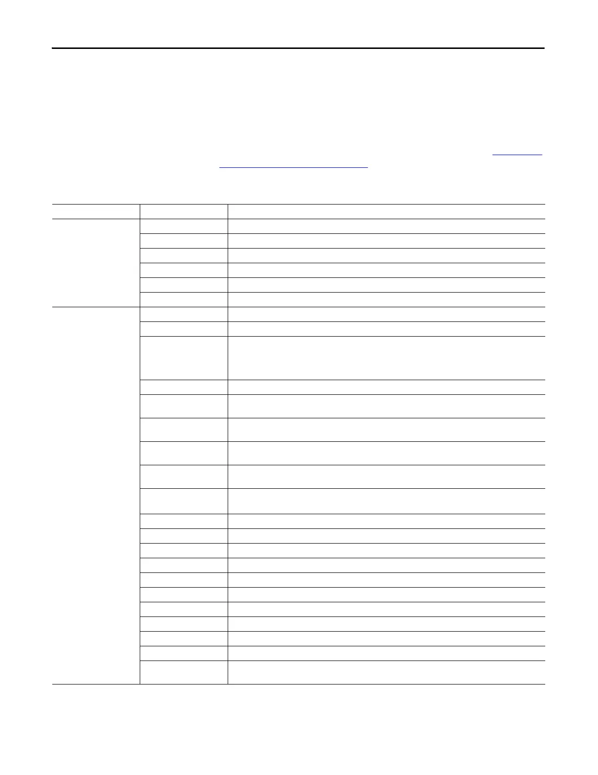
The following table lists the complete set of fault and status tags for
temperature-sensing modules. Check your modules configuration in the Logix
Designer application to determine which tags are available. Refer to Analog I/O
Module Tag Definitions on page 181 for specific information on applying tags to
each module.
Table 19 - Fault and Status Data Tags
Data Type Tag Name Triggering Event That Sets Tag
Fault
Fault
(1)
The owner-controller loses its connection to the module.
CJ[x].Underrange The cold junction for the channel is below 0 °C.
CJ[x].Overrange The cold junction for the channel is above 86 °C.
Ch[x].Fault The channel data quality is bad.
Ch[x].Underrange The channel data is beneath the absolute minimum for this channel.
Ch[x].Overrange The channel data is above the absolute maximum for this channel.
Status
CIPSyncValid
(1)
Indicates whether the module is synchronized to a valid CIP Sync time master on the backplane.
CIPSyncTimeout
(1)
Indicates whether a valid time master on the backplane has timed out.
CIPSyncOffsetJump
(1)
Indicates a significant jump, that is, 1 ms or greater, in the CST and CIP Sync times sent from the Time Master to the
module. (The Time Master sends the CST and CIP Sync times to the module every second.)
When a significant jump occurs, this tag value becomes 1 but changes to 0 a second later unless another jump
occurred.
Ch[x].Uncertain The channel data can be imperfect.
Ch[x].LLAlarm The I.Ch[x].Data tag value is less than the C.Ch[x].LLAlarmLimit tag value, the O.Ch[x].LLAlarmEn tag is set and alarms
are enabled for the channel.
Ch[x].LAlarm The I.Ch[x].Data tag value is less than the C.Ch[x].LAlarmLimit tag value, the O.Ch[x].LAlarmEn tag is set and alarms
are enabled for the channel.
Ch[x].HAlarm The I.Ch[x].Data tag value is greater than the C.Ch[x].HAlarmLimit tag value, the O.Ch[x].HAlarmEn tag is set and
alarms are enabled for the channel.
Ch[x].HHAlarm The I.Ch[x].Data tag value is greater than the C.Ch[x].HHAlarmLimit tag value, the O.Ch[x].HHAlarmEn tag is set and
alarms are enabled for the channel.
Ch[x].RateAlarm The absolute change between consecutive channel samples exceeds the C.Ch[x].RateAlarmLimit tag value.
This alarm only applies to enabled Process alarms.
Ch[x].CalibrationFault The channel is not calibrated or the last attempted calibration for this channel failed.
Ch[x].Calibrating The channel is currently being calibrated.
Ch[x].CalGoodLowRef A valid Low Reference signal has been sampled on this channel.
Ch[x].CalBadLowRef An invalid Low Reference signal has been sampled on this channel.
Ch[x].CalGoodHighRef An valid High Reference signal has been sampled on this channel.
Ch[x].CalBadHighRef An invalid High Reference signal has been sampled on this channel.
Ch[x].CalSuccessful Calibration on this channel is complete and the Calibrating state has been exited.
Ch[x].RateOfChange The change in channel data since last sample in Engineering Units/Second.
Ch[x].Data The channel data in scaled Engineering Units.
Timestamp
(1)
A 64-bit timestamp indicating when all 8 channels were last sampled in terms of CIPSync time.
RollingTimestamp
(1)
16-bit timestamp that ‘rolls’ from 0…32,767 ms. Compatible with existing PID instruction to automatically calculate
sample deltas. The timestamp changes when any one of the output channels is updated.
(1) This tag provides module-wide data and affects all channels simultaneously.

Table of Contents

Questions and Answers:

Allen-Bradley 1756-IR12 Specifications

General IconGeneral
BrandAllen-Bradley
Model1756-IR12
CategoryI/O Systems
LanguageEnglish

Summary

Chapter 1 Analog I/O Module Operation in the ControlLogix System

Configure a Module

Describes how to configure I/O modules using the Logix Designer application.

Input Module Operation

Explains how ControlLogix analog input modules broadcast data to their backplane.

Output Module Operation

Explains how RPI defines when a controller sends data to analog output modules.

Chapter 2 Analog I/O Module Features

Calibration

Details the methods for calibrating ControlLogix analog modules.

Chapter 3 1756-IF8I Isolated Analog Input Module

1756-IF8I Module Features

Lists the features of the 1756-IF8I Isolated Analog Input Module.

Fault and Status Reporting

Details how the module multicasts fault and status data via module tags.

Chapter 4 Temperature-sensing Analog Modules

Common Module Features

Lists common features available across temperature-sensing analog modules.

Process Alarms

Alerts when the module exceeds configured high or low limits for each channel.

Rate Alarm

Triggers if the rate of change between input samples exceeds a specified trigger point.

Cold Junction Compensation

Explains the need to compensate for thermoelectric effects in thermocouple measurements.

Chapter 5 1756-OF8I Isolated Analog Output Module

1756-OF8I Module Features

Lists the features of the 1756-OF8I Isolated Analog Output Module.

Redundant Owners

Allows a single controller to use redundant adapters or two controllers to coordinate output.

Configure the Output Module

Steps to configure output modules for redundant owner applications.

Troubleshooting

Provides guidance for troubleshooting common issues with output modules.

Chapter 6 Install ControlLogix Analog I/O Modules

Install the I/O Module

Describes how to install or remove a module while chassis power is applied.

Chapter 7 Configure ControlLogix Analog I/O Modules

Create a New Module

Steps to create a module in a Logix Designer application project.

Edit the Configuration

Explains how to use tabs in the New Module dialog box to edit configuration.

Configuration Tab

Details fields specific to module type for tasks like selecting I/O type and range.

Calibration Tab

Allows recalibration of the module to correct hardware inaccuracies.

Alarm Configuration Tab

Details fields specific to module type for disabling alarms and setting parameters.

Chapter 8 Calibrate the ControlLogix Analog I/O Modules

Calibrate Via Profile or Ladder

Describes calibrating modules online via software using Ladder Logic or Module Profile.

Calibrate the Input Modules

Details the multi-step process for calibrating input modules.

Calibrate the 1756-IF8I Module For Voltage Input Type

Provides steps for calibrating the 1756-IF8I module using voltage inputs.

Calibrate the Temperature-sensing Modules

Guides calibration for 1756-IRT8I, 1756-IR12, and 1756-IT16 modules.

Calibrate the Module for an RTD Input Type

Explains the process for calibrating modules with RTD input types using precision resistors.

Calibrate the Module for a Thermocouple Input Type

Provides steps for calibrating modules with thermocouple input types.

Calibrate the Output Module

Guides calibration for the 1756-OF8I module with current or voltage outputs.

Calibrate the 1756-OF8I Module for a Current Output Type

Details steps for calibrating the 1756-OF8I module for current output.

Chapter 9 Troubleshoot Your Module

Status Indicators for the 1756-IF8I Module

Explains the status indicators for the 1756-IF8I module.

Status Indicators for the 1756-IRT8I Module

Explains the status indicators for the 1756-IRT8I module.

Status Indicators for the 1756-IR12 Module

Explains the status indicators for the 1756-IR12 module.

Status Indicators for the 1756-IT16 Module

Explains the status indicators for the 1756-IT16 module.

Status Indicators for the 1756-OF8I Module

Explains the status indicators for the 1756-OF8I module.

Related product manuals