Rockwell Automation Publication 1756-UM540E-EN-P - December 2017 117
Install ControlLogix Analog I/O Modules Chapter 6
RTB Types
Each RTB comes with housing. The following RTB types work with
ControlLogix analog I/O modules:
• Cage Clamp RTB - Catalog Number 1756-TBCH
• Spring Clamp RTB - Catalog Number 1756-TBS6H
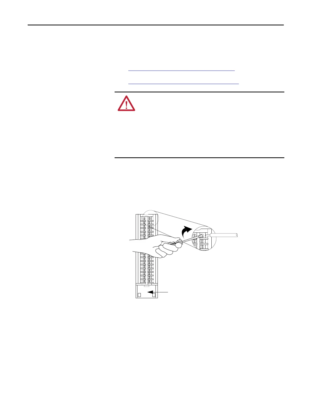
Cage Clamp RTB - Catalog Number 1756-TBCH
1. Strip 9.5 mm (3.8 in.) maximum length of wire.
2. Insert the wire into the open terminal on the side.
3. Turn the screw clockwise to close the terminal on the wire.
The open section at the bottom of the RTB is called the strain relief area. The
wiring from the connections can be grouped with a plastic tie.
ATTENTION: Consider the following when using the 1756-TBCH RTB:
• Do not wire more than two 0.33...1.3 mm
2
(22...16 AWG) conductors on any
single terminal.
• You can connect only one 2.1 mm
2
(14 AWG) conductor to any single terminal.
• Use only the same size wires with no intermixing of solid and stranded wire
types.
When using the 1756-TBS6H RTB, do not wire more than one conductor on any
single terminal.
 Loading...


