EasyManua.ls Logo

Allen-Bradley 1756-IR12 User Manual

Allen-Bradley 1756-IR12
226 pages
To Next Page IconTo Next Page
To Previous Page IconTo Previous Page
Page #211 background imageLoading...
Page #211 background image
Rockwell Automation Publication 1756-UM540E-EN-P - December 2017 211
Analog I/O Module Tag Definitions Appendix A
Redundant Owner
Configuration Tags
The redundant owner configuration tags are identical to the existing 1756-OF8I
configuration.
Redundant Owner Input Tag Layout
We added eight Input tags to the existing Input data layout. The bit tag field,
PartnerBits, increased from 2 bits to 10 bits to cover OwnerActive, Owner ID,
and Active/Claim/Ready status for the A and B controllers.
Redundant Owner Output Tag Layout
We added two Input tags in the Output data: a BOOL to reflect the COO bit
and another for the ROO bit.
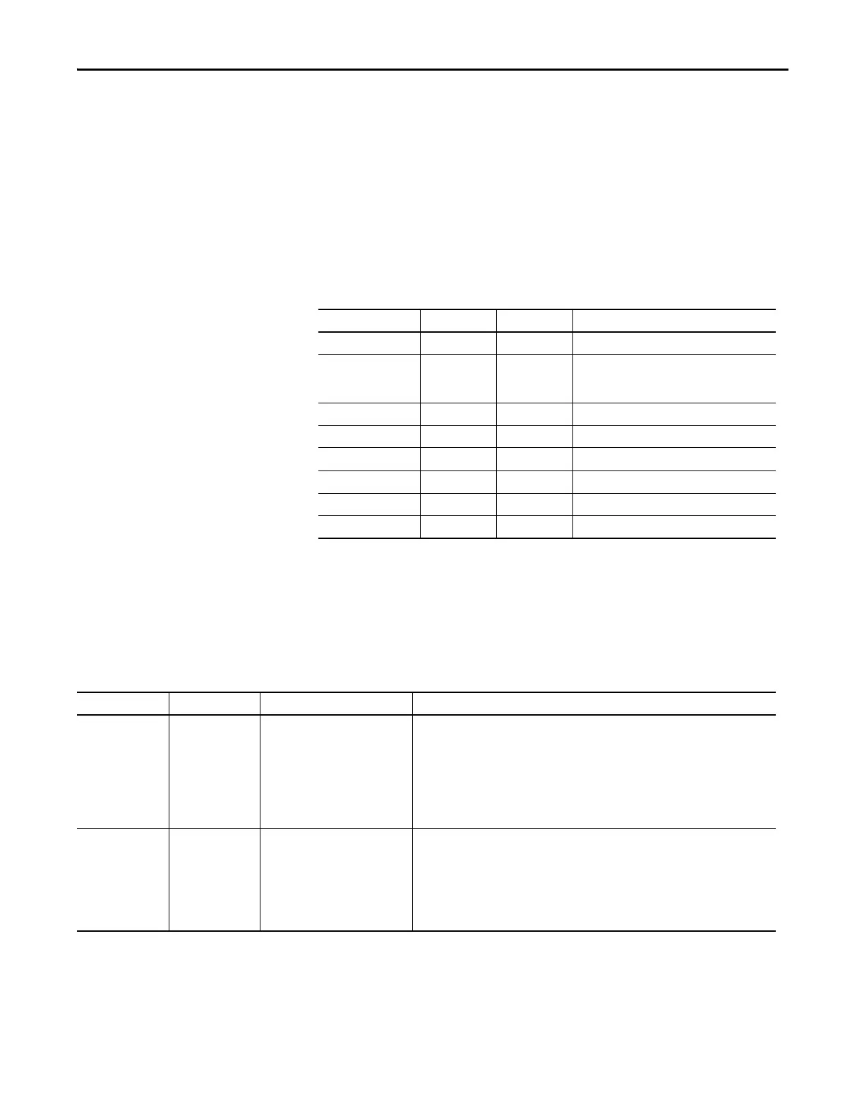
Table 41 - New Redundant Input Tag Description – 1756-OF8I
Field Data Type Legal Values Usage
OwnerActive BOOL B4 The Output has a Controlling Owner
OwnerID BOOL B5 Which Owner is Active (Controlling):
0 = Owner A
1 = Owner B
OwnerAConnected BOOL B6 Owner A is Connected.
OwnerAClaim BOOL B7 Owner A is claiming Outputs (COO).
OwnerAReady BOOL B8 Owner A is Ready to claim Outputs (ROO).
OwnerBConnected BOOL B9 Owner B is Connected.
OwnerBClaim BOOL B10 Owner B is claiming Outputs (COO).
OwnerBReady BOOL B11 Owner B is Ready to claim Outputs (ROO).
Table 42 - New Redundant Output Tag Description – 1756-OF8I
Field Data Type Legal Values Usage
OwnerClaim BOOL B0
0 = Not Requesting Ownership
1 = Claim Ownership
When set, indicates that the controller wants to Claim Ownership of the redundant
connection and have its outputs actively used.
If both Redundant Owners have COO set, the last originator application that transitioned
its COO flag from reset to set shall be the owner.
NOTE: Only a Rxd 0 to a 1 and not just the receipt of a new connection is considered such a
transition.
If neither Redundant Owner has COO set, then the highest ROO becomes Owner.
OwnerReady BOOL B1
0 = Not Ready to Own
1 = Ready to Own
Indicates the controller’s readiness for output ownership. A value of 1 indicates ready while
0 indicates the controller is not ready to own the outputs.
If neither controller has the COO bit set, the ROO determines the current owner.
If both controllers have COO=0 and ROO=0, then the outputs go to IDLE (Program
mode).
If both controllers have COO=0 and ROO=1, OwnerA will be active.

Table of Contents

Questions and Answers:

Allen-Bradley 1756-IR12 Specifications

General IconGeneral
BrandAllen-Bradley
Model1756-IR12
CategoryI/O Systems
LanguageEnglish

Summary

Chapter 1 Analog I/O Module Operation in the ControlLogix System

Configure a Module

Describes how to configure I/O modules using the Logix Designer application.

Input Module Operation

Explains how ControlLogix analog input modules broadcast data to their backplane.

Output Module Operation

Explains how RPI defines when a controller sends data to analog output modules.

Chapter 2 Analog I/O Module Features

Calibration

Details the methods for calibrating ControlLogix analog modules.

Chapter 3 1756-IF8I Isolated Analog Input Module

1756-IF8I Module Features

Lists the features of the 1756-IF8I Isolated Analog Input Module.

Fault and Status Reporting

Details how the module multicasts fault and status data via module tags.

Chapter 4 Temperature-sensing Analog Modules

Common Module Features

Lists common features available across temperature-sensing analog modules.

Process Alarms

Alerts when the module exceeds configured high or low limits for each channel.

Rate Alarm

Triggers if the rate of change between input samples exceeds a specified trigger point.

Cold Junction Compensation

Explains the need to compensate for thermoelectric effects in thermocouple measurements.

Chapter 5 1756-OF8I Isolated Analog Output Module

1756-OF8I Module Features

Lists the features of the 1756-OF8I Isolated Analog Output Module.

Redundant Owners

Allows a single controller to use redundant adapters or two controllers to coordinate output.

Configure the Output Module

Steps to configure output modules for redundant owner applications.

Troubleshooting

Provides guidance for troubleshooting common issues with output modules.

Chapter 6 Install ControlLogix Analog I/O Modules

Install the I/O Module

Describes how to install or remove a module while chassis power is applied.

Chapter 7 Configure ControlLogix Analog I/O Modules

Create a New Module

Steps to create a module in a Logix Designer application project.

Edit the Configuration

Explains how to use tabs in the New Module dialog box to edit configuration.

Configuration Tab

Details fields specific to module type for tasks like selecting I/O type and range.

Calibration Tab

Allows recalibration of the module to correct hardware inaccuracies.

Alarm Configuration Tab

Details fields specific to module type for disabling alarms and setting parameters.

Chapter 8 Calibrate the ControlLogix Analog I/O Modules

Calibrate Via Profile or Ladder

Describes calibrating modules online via software using Ladder Logic or Module Profile.

Calibrate the Input Modules

Details the multi-step process for calibrating input modules.

Calibrate the 1756-IF8I Module For Voltage Input Type

Provides steps for calibrating the 1756-IF8I module using voltage inputs.

Calibrate the Temperature-sensing Modules

Guides calibration for 1756-IRT8I, 1756-IR12, and 1756-IT16 modules.

Calibrate the Module for an RTD Input Type

Explains the process for calibrating modules with RTD input types using precision resistors.

Calibrate the Module for a Thermocouple Input Type

Provides steps for calibrating modules with thermocouple input types.

Calibrate the Output Module

Guides calibration for the 1756-OF8I module with current or voltage outputs.

Calibrate the 1756-OF8I Module for a Current Output Type

Details steps for calibrating the 1756-OF8I module for current output.

Chapter 9 Troubleshoot Your Module

Status Indicators for the 1756-IF8I Module

Explains the status indicators for the 1756-IF8I module.

Status Indicators for the 1756-IRT8I Module

Explains the status indicators for the 1756-IRT8I module.

Status Indicators for the 1756-IR12 Module

Explains the status indicators for the 1756-IR12 module.

Status Indicators for the 1756-IT16 Module

Explains the status indicators for the 1756-IT16 module.

Status Indicators for the 1756-OF8I Module

Explains the status indicators for the 1756-OF8I module.

Related product manuals