Rockwell Automation Publication 1756-UM540E-EN-P - December 2017 47
1756-IF8I Isolated Analog Input Module Chapter 3
Digital Filter
The digital filter smooths input data noise transients on each input channel.
This value specifies the time constant for a digital, first-order lag filter on the
input. It is specified in units of milliseconds. A value of 0 (zero) disables
the filter.
The digital filter equation is a classic, first order lag equation.
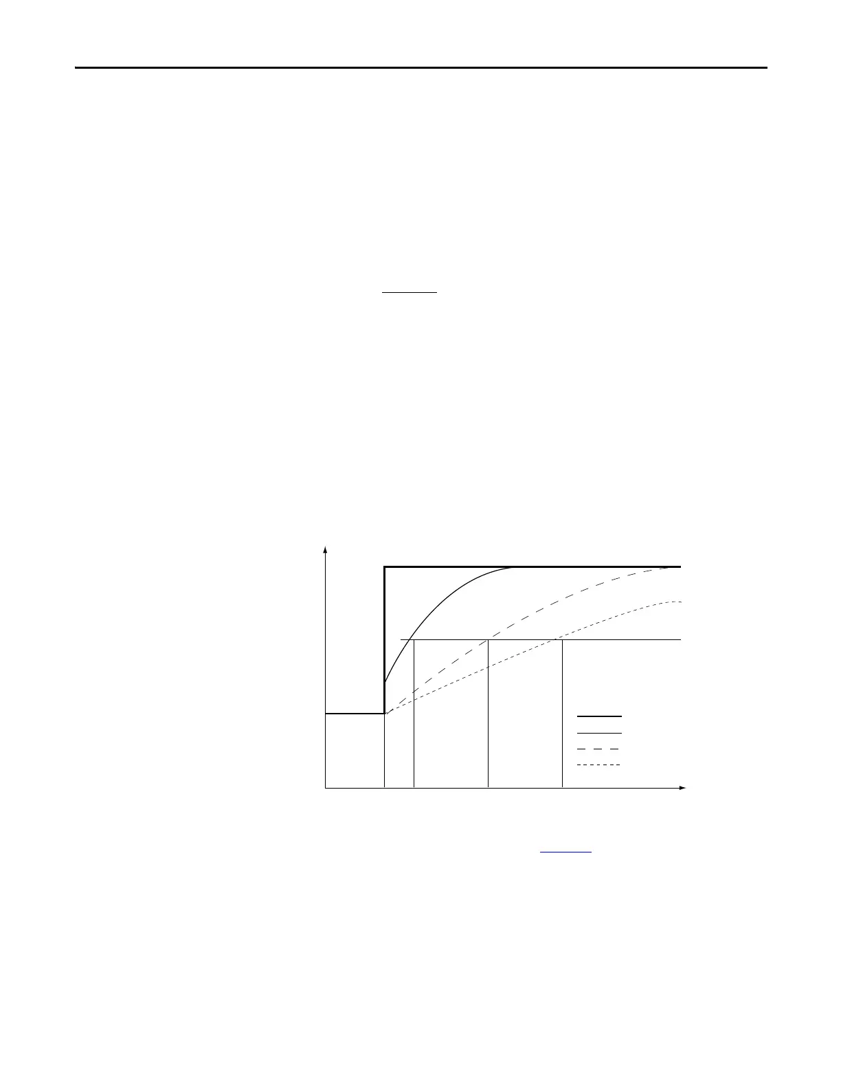
As shown in the following graphic, by using a step input change to illustrate the
filter response, you see that 63.2% of the total response is reached when the
digital filter time constant elapses. Each additional time constant achieves 63.2%
of the remaining response.
To see where to set the Digital Filter, see page 131
.
Y
n
= Y
n
-1
+X
n
- Y
n
-1
[∆ t]
∆
t + TA
Y
n
= Present output, filtered peak voltage (PV)‘
Y
n
-1
= Previous output, filtered PV
∆
t = Module channel update time (seconds)
TA = Digital filter time constant (seconds)
X
n
= Present input, unfiltered PV
0 0.01 0.5 0.99 Time in Seconds
100%
63%
0
Amplitude
Unfiltered Input
TA = 0.01 second
TA = 0.5 second
TA = 0.99 second
 Loading...


