66 Rockwell Automation Publication 1756-UM540E-EN-P - December 2017
Chapter 4 Temperature-sensing Analog Modules
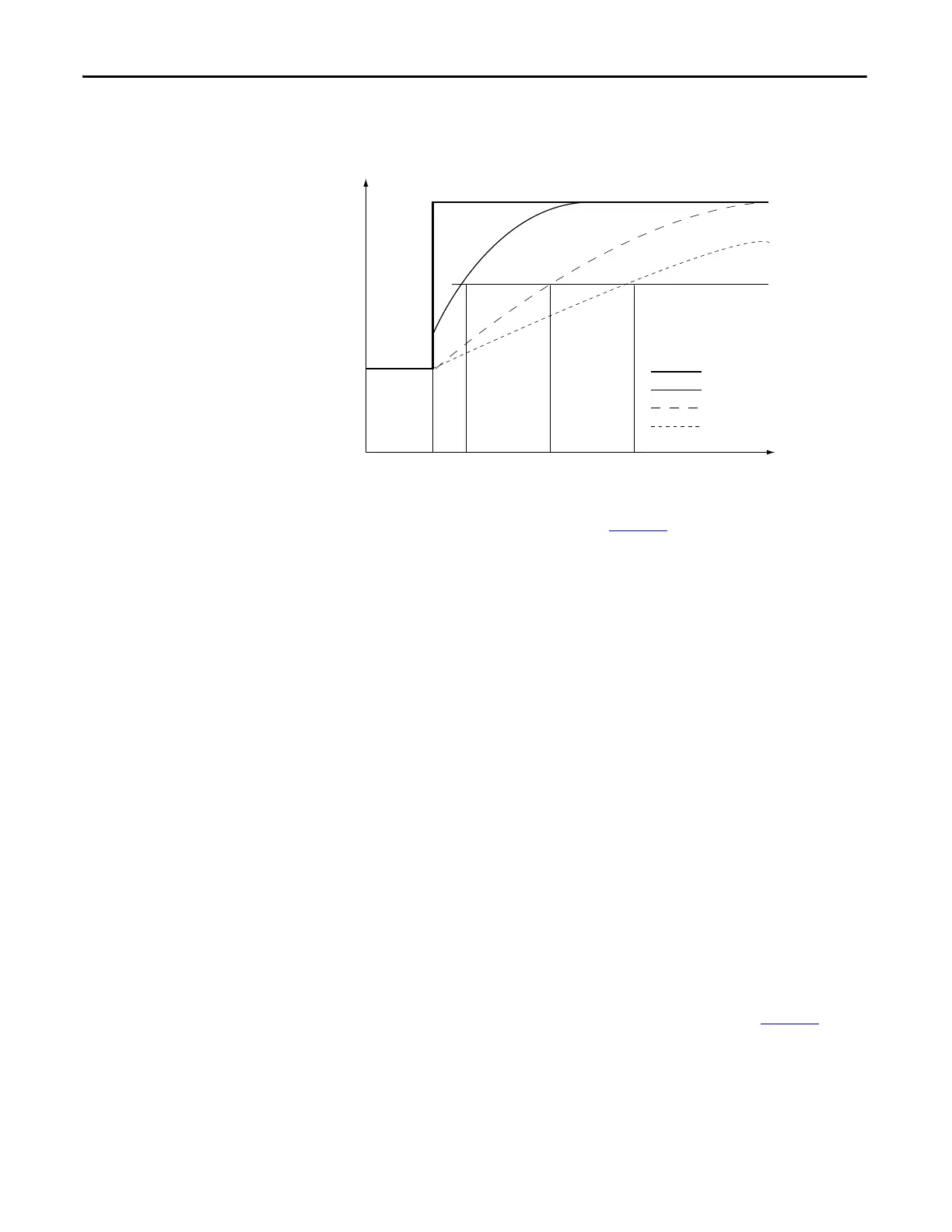
By using a step input change to illustrate the filter response, you can see that when
the digital filter time constant elapses, 63.2% of the total response is reached.
Each additional time constant achieves 63.2% of the remaining response.
To see where to set the Digital Filter, see page 131
.
Process Alarms
The 1756-IRT8I supports process alarms. Process alarms alert you when the
module has exceeded configured high or low limits for each channel. These are
set at four, user-configurable, alarm trigger points:
• High high
• High
• Low
• Low low
You can enable or disable Process Alarms individually via the Output tags for
each channel. When a module is added to your Logix Designer application
project and tags are created, the Alarms are disabled by default.
Each individual Process Alarm enable tag, that is, O.Ch[x].LLAlarmEn,
O.Ch[x].LAlarmEn, O.Ch[x].HAlarmEn and O.Ch[x].HHAlarmEn, is disabled
when the module is created. You must enable the tags in the Output Data to
allow the individual alarm to trigger.
If an enable bit of a Process Alarm is not set, the corresponding Input Process
Alarm never triggers. To see where to set the Process Alarms, see page 137
.
0 0.01 0.5 0.99 Time in Seconds
1672
100%
63%
0
Amplitude
Unfiltered Input
TA = 0.01 s
TA = 0.5 s
TA = 0.99 s
 Loading...


