19
www.amcelettronica.com
KX series v.1.70
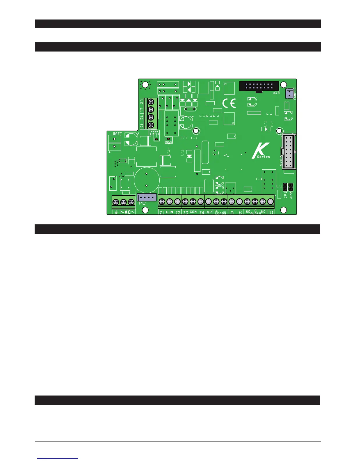
MAIN BOARD K4 - K8 - K8PLUS
The main board is the core of the system, all modules are be connected to it, plug the card directly or via RS-485 serial bus.
The following characteristics:
K4
BOARD DESCRIPTION
ERRORE:MfgAppDate
UNLESS OTHERWISE SPECIFIED:
CHECKED
SIZE
APPLICATION
TITLE:
PROPRIETARY AND CONFIDENTIAL
INTERPRET GEOMETRIC
TOLERANCING PER:
Q.A.
ERRORE:DrawnBy
ERRORE:QAApproval
FINISH
ERRORE:QAAppDate
ERRORE:COMPANYNAME
DWG. NO.
DATE
USED ON
A
DIMENSIONS ARE IN INCHES
TOLERANCES:
FRACTIONAL
ANGULAR: MACH
BEND
TWO PLACE DECIMAL
THREE PLACE DECIMAL
ERRORE:Revision
NEXT ASSY
MATERIAL
NAME
REV
DO NOT SCALE DRAWING
SCALE: 1:1
K4
ENG APPR.
THE INFORMATION CONTAINED IN THIS
DRAWING IS THE SOLE PROPERTY OF
<INSERT COMPANY NAME HERE>. ANY
REPRODUCTION IN PART OR AS A WHOLE
WITHOUT THE WRITTEN PERMISSION OF
<INSERT COMPANY NAME HERE> IS
PROHIBITED.
ERRORE:EngineeringApproval
ERRORE:CheckedBy
COMMENTS:
ERRORE:ManufacturingApproval
DRAWN
ERRORE:CheckedDate
ERRORE:DrawnDate
ERRORE:EngAppDate
MFG APPR.
SHEET 1 OF 1
2 1
A
B
A
B
12
<COMPANY NAME>
BATTERY + - = battery recharge terminals
L1 - L2 = ATS2 phone line terminal outs (carrier out)
T1 - T2 = terminals for internal local telephones (home telephones user)
AC = main power by transformer 18Vac (available 25VA - 30VA)
Z1-Z2-Z3-Z4 = zones
COM = negative reference for zones
PC = adpater socket for programming pc software
AP = Tamper line with negative reference
LOADS (+ -) = power supply AUX 13.8 Vcc for external device (eg. sirens)
A B = (RS 485) = bus terminals for peripheral connection (see chapter fo bus connection)
ALARM (nc - no - com) = terminal for siren, free relay contact
OUT1 = PGM programmable open-collector output 100mA max current
EXP = socket for plug modules (XGSM, GPRS, IP boards)
TAMPER connector = for mechanical antiopening tamper (option)
Led on board:
HOOK LED = red color led is in ON when panel take PSTN line (PSTN HOOK on)
PSTN STATUS LED:
- STEADY YELLOW: phone line in standby stautus (no problems)
- FLASHING YELLOW : PSTN calling status
K4 TERMINALS
JP1 AND JP2 JUMPER ON BOARD
These jumpers must remain open
Are used for updating the firmware and total reset of the parameters. The guide for these is in the tool for upgrade FW panel.
 Loading...