26
www.amcelettronica.com
KX series v.1.70
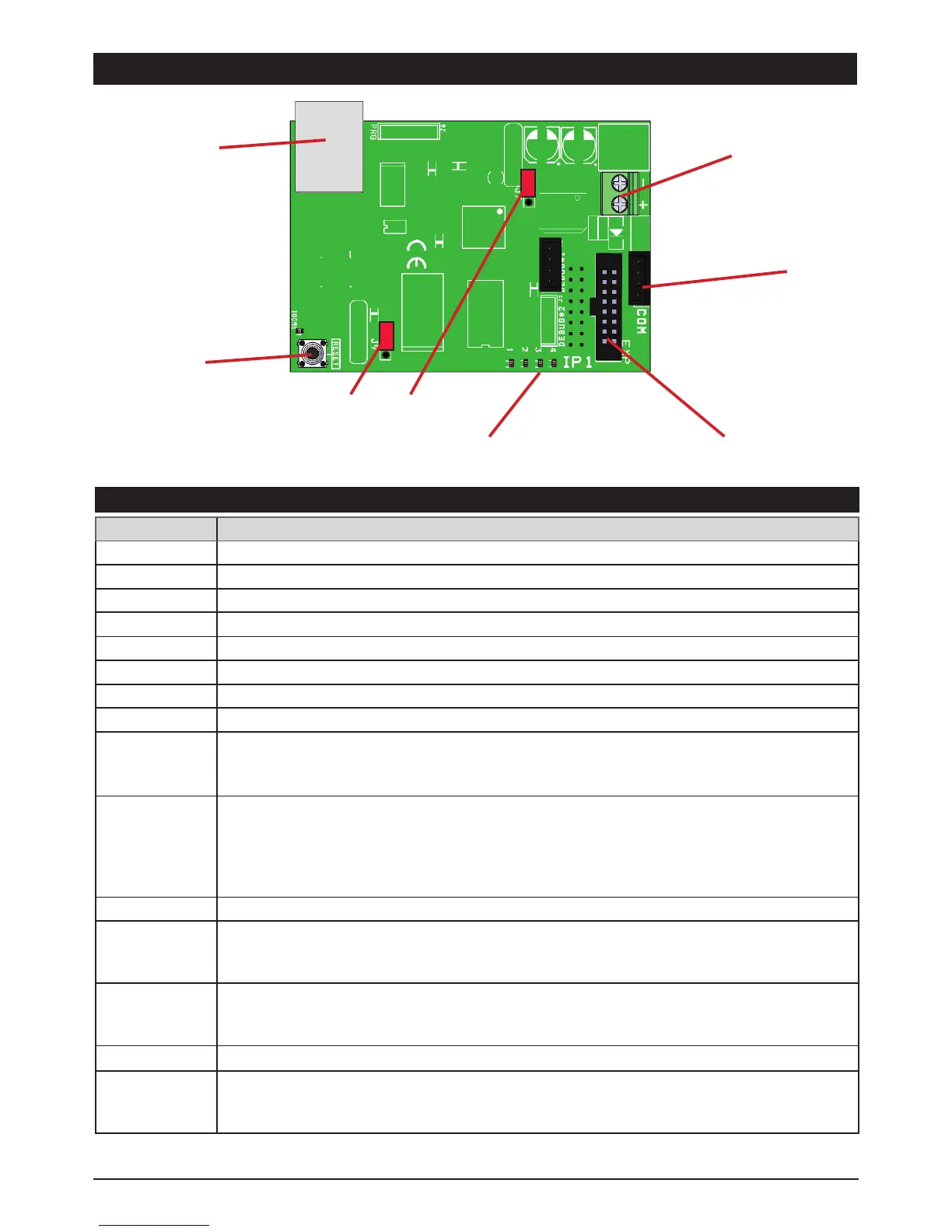
IP1 BOARD DESCRIPTION
SPECIFICATIONS IP BOARD
SPECIFICATIONS
ip board
Power supply: 5-13,8Vcc
Current: 163mA @ 12V
MPU: ARM® Cortex™-M3
RAM: 512KB
ROM1: 8MB
ROM2: 64KB
SYS: RTOS v7.2
LAN: 10/100 BASE TX IEEE 802.1x Full Duplex
PROTOCOL: Base: TCP/IP
Encrypt: TLS/SSL
Data: AMC Protocol V1.0 for system serie C-X-K
LED: GREEN ON = OK “comunication to system ok”.
GREEN BLINKING = FAIL “no comunication to system” (Enable IP expansion on menu)
YELLOW BLINKING = system running.
RED 1 BLINKING = FAIL to connect to cloud server. “wait to connetting”
RED2 BLINKING = Cable not connect;
BUTTON: RESET = ONLY LAN BOARD
J7-J9: NORMAL RUNING.
JP7: 1-2 close
JP9: 1-2 close
J7-J9: FIRMWARE UPDATE.
JP7: 2-3 close
JP9: 2-3 close
COM: DAPTER: COM-S,COM-USB (only for FIRMWARE UPDATE).
classification ATS3/SP3 refered to EN 50136-2:2013 (
to ensure the classification SP3 the periodic test call must be pro-
grammed for work every 30’ minutes, or for have classification SP2, the periodic test call can be program-
med for work every 25h)
Ethernet plug
reset button
Indications led Socket for Xgprs
upgradeFW socket
External power supply
needed for upgrade FW
normal running
 Loading...