36
www.amcelettronica.com
KX series v.1.70
The control unit has 1/2 outputs, which can be expanded by using the optional Expus module.
The module must be connected to the BUS-485 line with the respective terminals A, B, +12V and -.
Before providing power to the system, in order to differentiate the peripherals, you must address them using their microswitches
(DIP-SWITCHES), referring to the following figure.
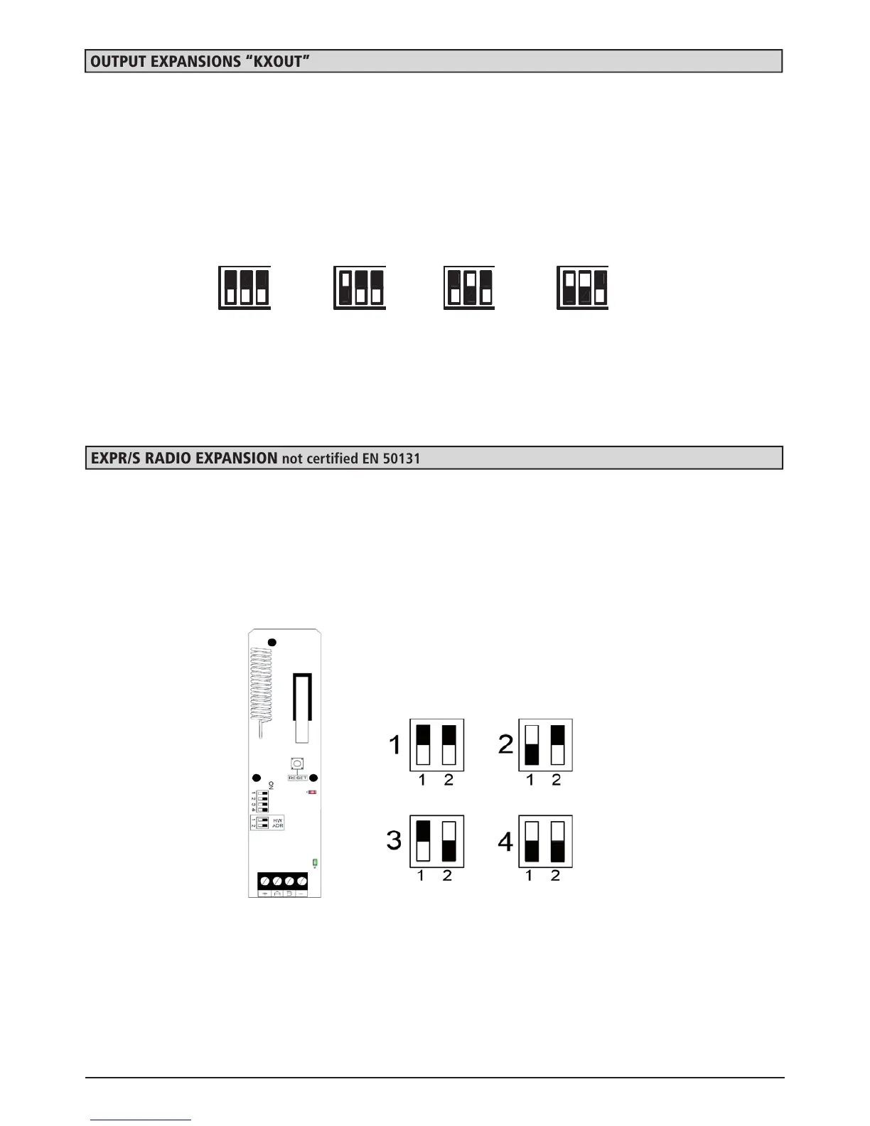
OUTPUT exPansiOns “KxOUT”
For the use of O.C. outputs, refer to the manual, paragraph CONNECTIONS - OUTPUTS.
DIP-Switch Configuration
Please Note: in CONFIGURATION 1 ALL DIPSWITCHES ARE OFF
The 32 device radio receiver is connected to the control unit through the bus 485 line. A maximum of 2 can be connected to the
control unit.
expr/s radio expansion not certified EN 50131
There are 2 pairs of dipswitches with 2 and 4 selectors:
- HD ADR = the address
- Tied to the radio receiver section
Follow the drawing below for coding the bus address.
Note: dipswitches with 4 selectors only use dipswitch no. 3 which enables the cover anti-opening protection.
(LEAVE THE OTHER DIPSWITCHES OFF)
DIP-Switch Configuration
1
4
7
*
2
5
8
0
3
6
9
#
CANC
IMPIANTO
MEMORIA
CONTROLLO
+12V
Vdc
1
-
2
A
3
B
4
D E F
6 7
0 A
2 3
8
B
4
Configurazione DIP-SWITCH
DIP-SWITCH
C
5
9
1
Please Note: in CONFIGURATION 1 ALL DIPSWITCHES ARE OFF
 Loading...