21
www.amcelettronica.com
KX series v.1.70
MAIN BOARD X 412 - X 824 - 864
The main board is the core of the system, all modules are be connected to it, plug the card directly or via RS-485 serial bus.
The following characteristics:
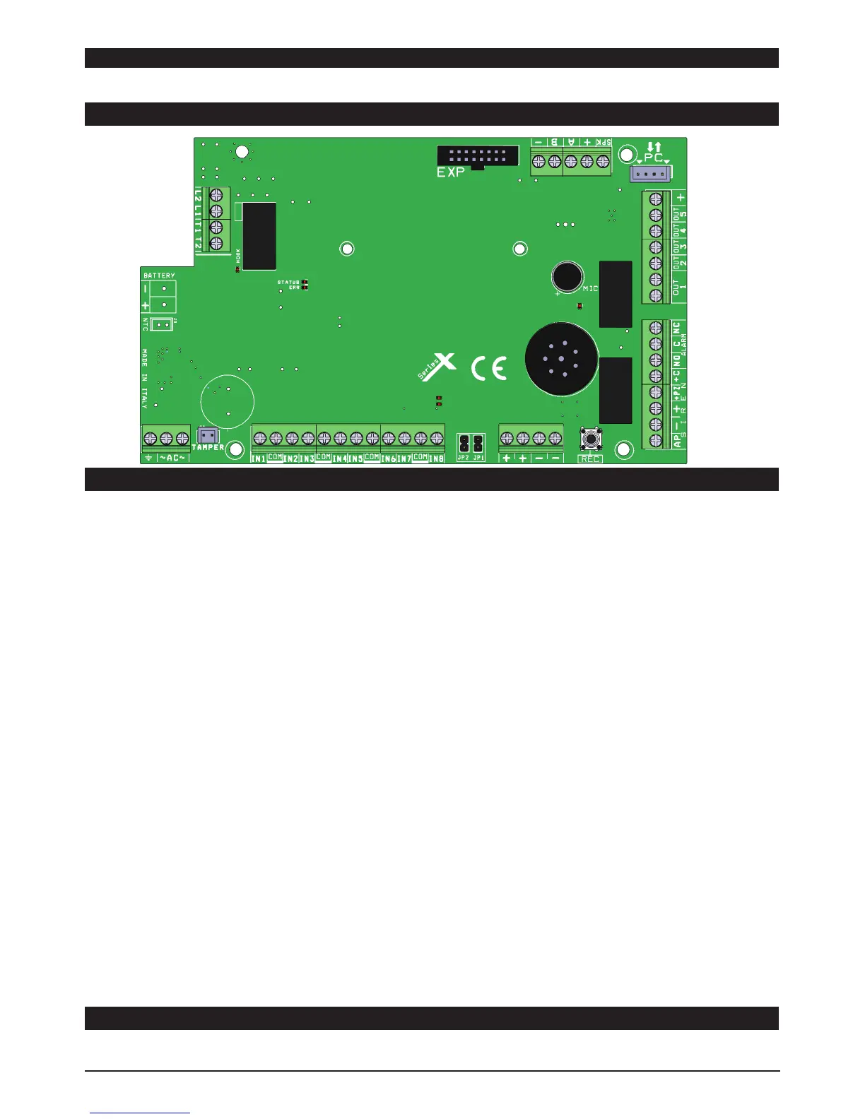
X PANEL BOARD
BATTERY + - = battery recharge terminals
L1 - L2 = ATS2 phone line terminal outs (carrier out)
T1 - T2 = terminals for internal local telephones (home telephones user)
AC = main power by transformer 18Vac (available 25VA - 30VA)
Z1-2-3-4-5-6-7-8= zones
COM = negative reference for zones
PC = adpater socket for programming pc software
AP = Tamper line with negative reference
LOADS (+ -)= power supply AUX 13.8 Vcc for external device
+ A B - (RS 485) = bus terminals for peripheral connection (see chapter fo bus connection)
+C = terminal for siren in missing positive mode
+PZ = for lounch piezo siren, give postive mode
ALARM (nc - no - com) = terminal for siren, free relay contact
0UT1= Free conatct relay programmable output (30Vcc - 2A max)
OUT2 to 5 = PGM programmable open-collector output 100mA max current
EXP = socket for plug modules (XGSM, GPRS, IP boards)
TAMPER connector = for mechanical antiopening tamper (option)
Led on board:
HOOK red led = ON PSTN HOOK enable
STATUS yellow led phone line status:
- Steady = pstn ready in stand by
- Blink = pstn active in call
- OFF = no presence pstn line
ERR red led:
- Steady = troubble (no pstn line - no GSM - no 230Vac)
- Blink = no battery - battery low charge
- OFF = no anomalies
MIC red led = only blink during on record audio
XPANELS TERMINALS
JP1 AND JP2 JUMPER ON BOARD
These jumpers must remain open
Are used for updating the firmware and total reset of the parameters. The guide for these is in the tool for upgrade FW panel.
 Loading...