10
1.8 7 7. 8 7 7. 2 2 69 BLACKBOX.COM
NEED HELP?
LE AVE THE TECH TO US
LIVE 24/7
TECHNICAL
SUPPORT
1.8 7 7.8 7 7.2269
CHAPTER 1: SPECIFICATIONS
1.2.3 COA XIAL
NOTE: A point-to-point connection is required.
TABLE 1-6. INTERCONNECT COAXIAL CABLE TYPES
CABLE TYPE DESCRIPTION
MIni coaxial cable AWG 18 RG 6, 75 ohms impedance
TABLE 1-7. MAXIMUM COAXIAL CABLE LENGTH
BANDWIDTH MAXIMUM ACCEPTABLE CABLE LENGTH
0.270 Gbit/s 1312 ft. (400 m)
1.485 Gbit/s 459 ft. (140 m)
2.970 Gbit/s 394 ft. (120 m)
TABLE 1-8. TYPE OF CONNECTOR
CONNECTOR MINI BNC CONNECTOR
1.3 CONNECTOR PINOUTS
1.3.1 CPU BOARD
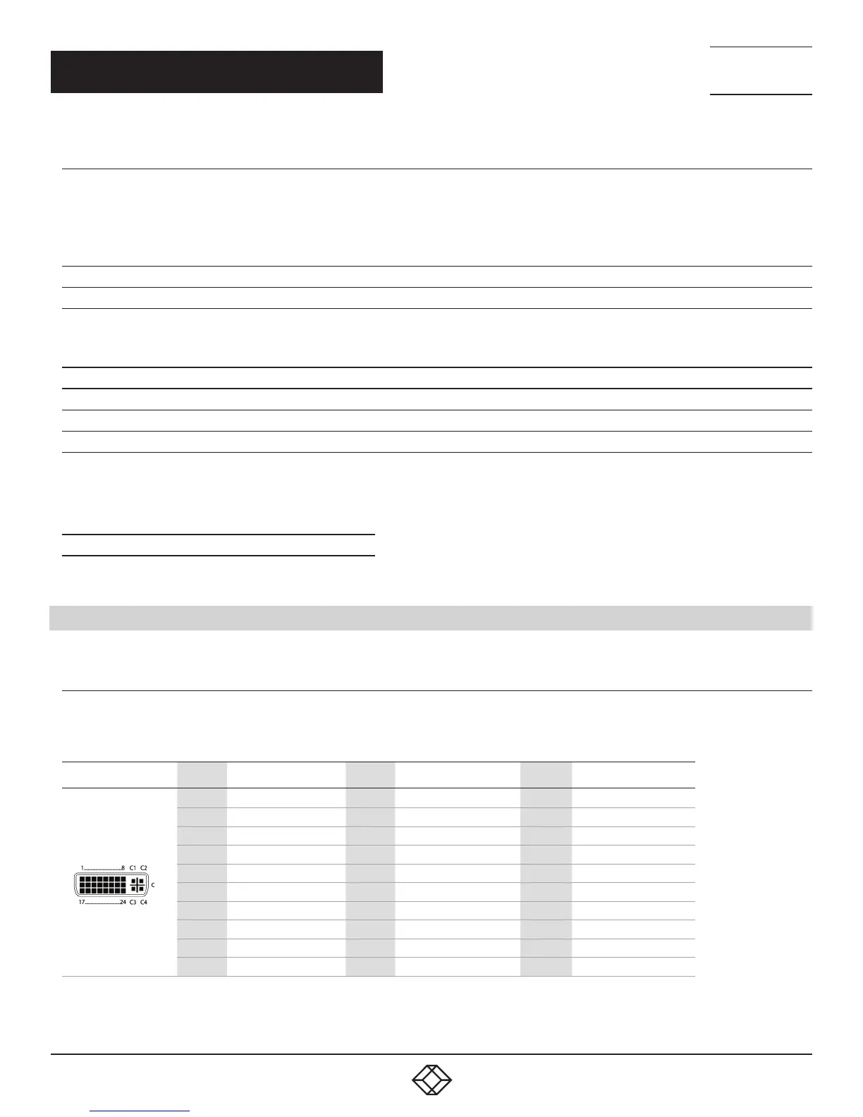
TABLE 1-9. DVI-D SINGLE LINK CONNECTOR PINOUT
PICTURE PIN SIGNAL PIN SIGNAL PIN SIGNAL
1 T.M.D.S. data 2- 9 T.M.D.S. data 1- 17 T.M.D.S. data 0-
2 T.M.D.S. data 2+ 10 T.M.D.S. data 1+ 18 T.M.D.S. data 0+
3 T.M.D.S. data 2 GND 11 T.M.D.S. data 1 GND 19 T.M.D.S. data 0 GND
4 not connected 12 not connected 20 not connected
5 not connected 13 not connected 21 not connected
6 DDC input (SCL) 14 +5 VDC high impedance 22 T.M.D.S. clock GND
7 DDC output (SCL) 15 GND 23 T.M.D.S. clock +
8 Internal use 16 Hot Plug recognition 24 T.M.D.S. clock -
C1 Internal use C3 Internal use
C2 not connected C5 GND C4 Internal use
 Loading...