11
1.8 7 7. 8 7 7. 2 2 69 BLACKBOX.COM
NEED HELP?
LE AVE THE TECH TO US
LIVE 24/7
TECHNICAL
SUPPORT
1.8 7 7.8 7 7.2269
CHAPTER 1: SPECIFICATIONS
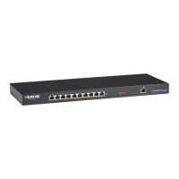
TABLE 1-10. USB TYPE A CONNECTOR PINOUT
PICTURE PIN SIGNAL COLOR
1 VCC (+5 VDC) Red
2 Data - White
3 Data + Green
4 GND Black
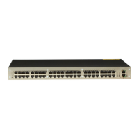
TABLE 1-11. DB9 SERIAL RS-232, DTE CONNECTOR PINOUT
PICTURE PIN SIGNAL PIN SIGNAL
1 not connected 6 DSR
2 RxD 7 RTS
3 TxD 8 CTS
4 DTR 9 not connected
5 GND — —
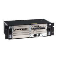
TABLE 1-12. RJ-45 CONNECTOR PINOUT
PICTURE PIN SIGNAL PIN SIGNAL
1 D1+ 6 not connected
2 D1- 7 D2-
3 D2+ 8 not connected
4 not connected 9 not connected
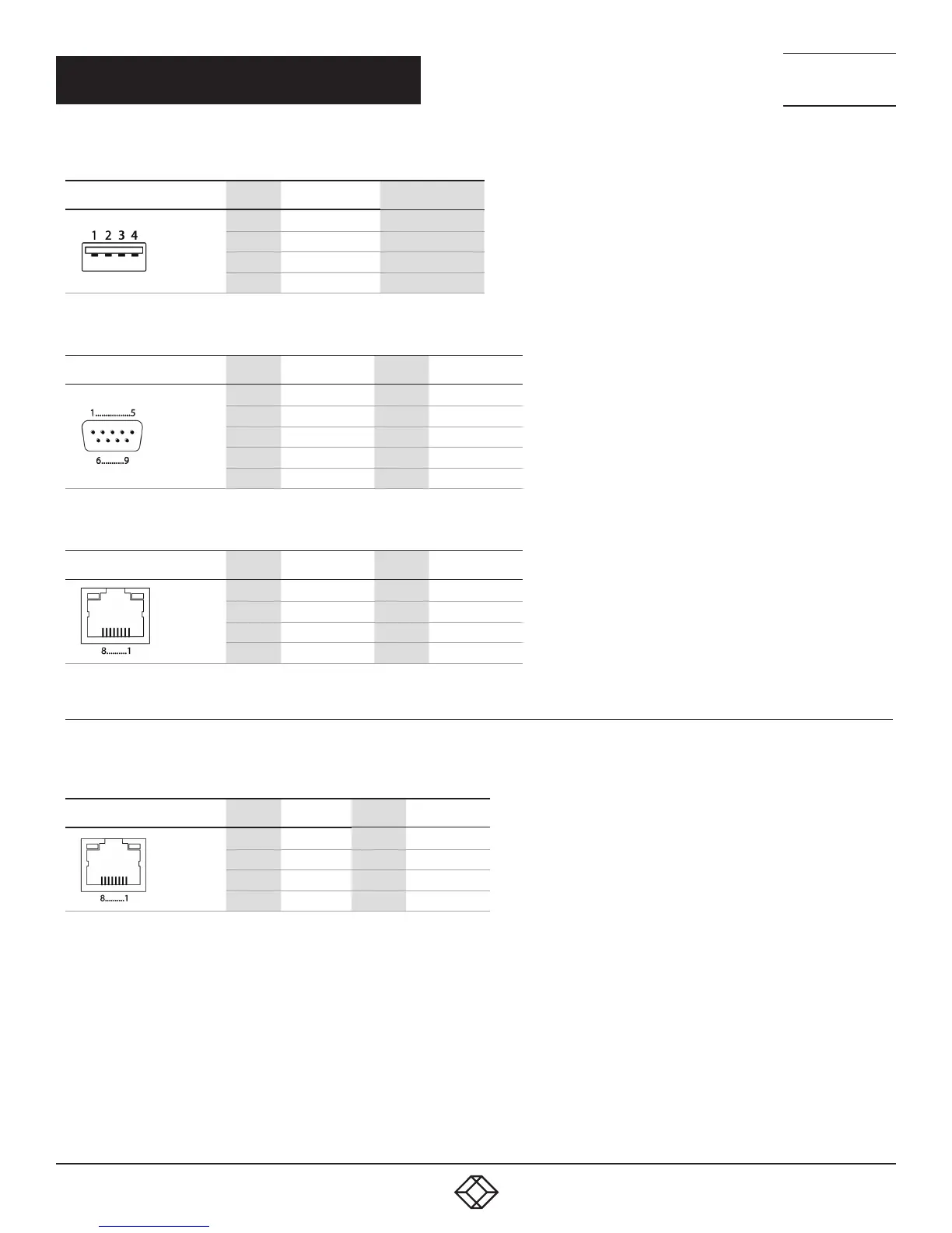
1.3.2 I/O PORT CATX
TABLE 1-13. RJ-45
PICTURE PIN SIGNAL PIN SIGNAL
1 D1+ 5 D3-
2 D1- 6 D2-
3 D2+ 7 D4+
4 D3+ 8 D4-
 Loading...