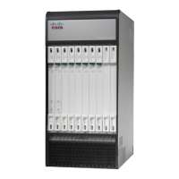
Replace the Upper Fan Tray
Step 1
At the rear of the chassis, remove the cover panel below the vent panel at the top of the chassis. Firmly grasp the side
edges of the panel and pull up and away to unsnap the panel. Put the panel safely aside.
Step 2
Loosen the knurled screws and remove the upper fan tray access panel from the chassis. Place it safely aside.
Step 3
Use a #1 Phillips screwdriver to loosen the two screws that secure the fan tray to the chassis.
Step 4
Grasp screw posts on the ends of the unit and pull the failed fan tray unit from the chassis.
Step 5
Place the failed fan tray unit safely aside.
Step 6
Align the replacement fan tray within the upper chassis opening. With the unit resting on the bottom rail of the opening,
push inward until the rear connector is firmly seated in the midplane. If the ASR 5500 is powered up, the fans should
begin spinning.
Step 7
Tighten the screws that secure the fan tray to the chassis.
Step 8
Reinstall the access panel.
Step 9
Reinstall the top cover panel by aligning it over the balled posts and snapping it in place.
Step 10
For additional instructions, refer to Returning Failed Components, on page 147.
ASR 5500 Installation Guide
132
Replaceable Components
Replacing Rear Fan Trays

 Loading...


