Cable management tray2Cable management bracket1
Cable guides3
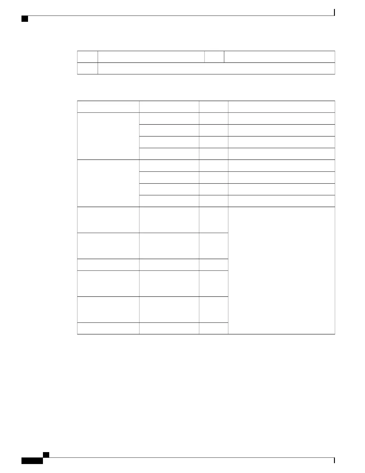
Table 27: CMS Routing Paths
DestinationNotesCable GuideCard
Bottom DC (ports 20 to 29)
—
3AMIO or UMIO, slot 5
1GbE (ports 1 and 2)
—
3A
Top DC (ports 10 to 19)13B or 3C
Future23C
Bottom DC (ports 20 to 29)
—
3DMIO or UMIO, slot 6
1GbE (ports 1 and 2)
—
3D
Top DC (ports 10 to 19)13E or 3F
Future23F
1GbE
(ports 1
and 2)
—
3D
Top DC
(ports 10
to 13)
13E or 3F
Future23F
1GbE
(ports 1
and 2)
—
3D
Top DC
(ports 10
to 13)
13E or 3F
Future23F
Notes:
1
If cable guide has been removed.
2
Already in use if cable guide has been removed.
CMS Procedure for Replacing ASR 5500 Circuit Cards
When the cable management tray is installed, the procedure for removing circuit cards from the ASR 5500
chassis varies from that described in the Circuit Cards section of the Replaceable Components chapter.
ASR 5500 Installation Guide
164
Cable Management System Installation
CMS Procedure for Replacing ASR 5500 Circuit Cards

 Loading...


