xStack® DES-3200 Series Layer 2 Managed Fast Ethernet Switch
230
• MAC address: The Switch’s system MAC address.
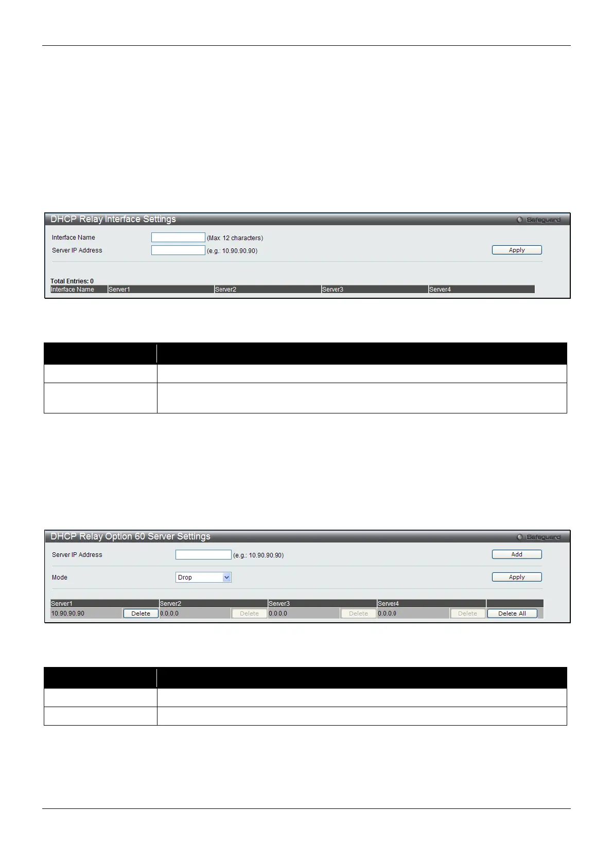
DHCP Relay Interface Settings
This window is used to set up a server, by IP address, for relaying DHCP information to the Switch. The user may
enter a previously configured IP interface on the Switch that will be connected directly to the DHCP server using
this window. Properly configured settings will be displayed in the DHCP Relay Interface Table at the bottom of the
window, once the user clicks the Apply button. The user may add up to four server IPs per IP interface on the
Switch. Entries may be deleted by clicking the corresponding Delete button.
To view this window, click Network Application > DHCP > DHCP Relay > DHCP Relay Interface Settings as
shown below:
Figure 9-4 DHCP Relay Interface Settings window
The fields that can be configured are described below:
Parameter Description
The IP interface on the Switch that will be connected directly to the Client.
Server IP Address
Enter the IP address of the DHCP server. Up to four server IPs can be configured per
Click the Apply button to accept the changes made.
DHCP Relay Option 60 Server Settings
This window is used to configure the DHCP relay option 60 server parameters.
To view this window, click Network Application > DHCP > DHCP Relay > DHCP Relay Option 60 Server
Settings as shown below:
Figure 9-5 DHCP Relay Option 60 Server Settings window
The fields that can be configured are described below:
Parameter Description
Enter the DHCP Relay Option 60 Server Relay IP Address.
Use the drop-down menu to select the DHCP Relay Option 60 Server mode.
Click the Add button to add a new entry based on the information entered.
Click the Apply button to accept the changes made.
Click the Delete button to remove the specific entry.
Click the Delete All button to remove all the entries listed.
 Loading...