ASDA Series Application Note Application Examples
March, 2015 3-5
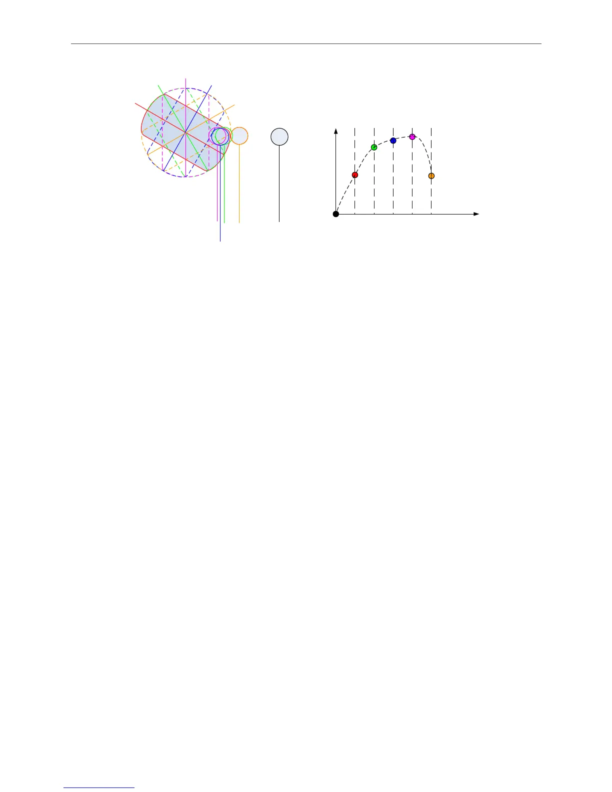
M1
M2
M3
M4
M5
E1
E2
E3
E4
E5
E0
M0
Slave position
(Round compression axis)
Master position
(Rectangle carrier)
M1 M2 M3 M4 M5M0
E0
E1
E2
E3
E4
E5
Figure 3.1.2 Creating an E-Cam Curve
3.1.2.2 Settings for the Route of Master Axis (Rectangle Carrier)
When creating the E-Cam curve, the moving distance of the rectangle carrier has to be divided
into equal parts. In this example, the servo generates 10000 pulses per circle because E-gear
ratio is set to 1 : 1. However, in the real mechanism, the master axis, ASDAS-A series servo
motor, will go through a decelerator that reduce the speed to 1/5 of the original. Therefore, the
rectangle carrier will make one full circle until the servo motor makes 5 rotations. To create an
E-Cam curve with 50 points, the motion of the master axis has to be divided into 50 equal parts.
See its calculation below.
The pulse number generated when the rectangle carrier travels one circle:
10000 x 5 = 50000 (pulses)
The required pulse number (distance) of the master axis to travel each point on the E-Cam curve
corresponding to the slave axis:
50000 / 50 = 1000 (pulses)
So, the rectangle carrier will send 1000 pulses to the slave axis whenever it travels one point.
Then, it has to stop and wait for the slave axis to do sampling.
The more sampling points there are, the more precise E-Cam curve it is. On the other hand, the
time it takes will be longer. (ASDA-A2 series servo drive provides E-Cam curves with maximum
720 points.)

 Loading...


