Application Examples ASDA Series Application Note
3-102 March, 2015
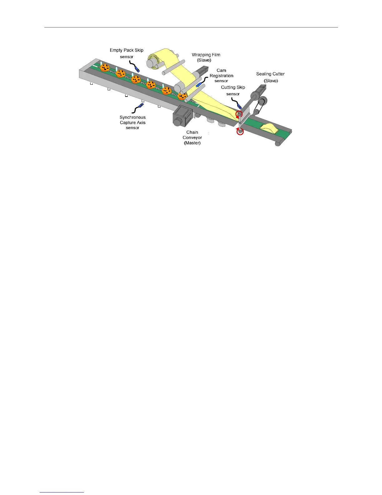
Figure 3.8.1 Systematic Diagram of Packing Machine
3.8.3 Servo System Setup
3.8.3.1 Configuration
The pulse of master axis on two camshafts is from the output pulse of material feeding axis. The
film feeding axis and cutter axis can therefore operate in accordance with the speed of material
feeding axis by pulse by-pass function.
In order to synchronize the phase of different axis of the whole system, there are two functions of
phase adjustment.
Synchronous Capture Axis: this function will be enabled on film feeding axis and cutter axis.
The detected signal of positioning on master axis connects to DI7 of two axes. Since DI7 is
the high-speed pin input, synchronous capture axis has to connect to high-speed pin. There
is no need to set DI7 as specific DI function, (For instance, the function code can use the
default 0x100.).
Cam Positioning: this function is used in film feeding axis. This sensor detects the mark of
the wrapping film and sends signals back to the film feeding axis as the reference for
positioning. Signal can enter via any DI in one condition; DI has to be set to 0x35 (signals
normally close) or 0x135 (signals normally open).

 Loading...


