ASDA Series Application Note Introduction of E-Cam Operation
March, 2015 2-7
Master
CN1
OA,
/OA,
OB,
/OB
Slave 1
CN5
Opt A,
/Opt A,
Opt B,
/Opt B
Slave 1
CN1
OA,
/OA,
OB,
/OB
Slave 2
CN5
Opt A,
/Opt A,
Opt B,
/Opt B
Slave 2
CN1
OA,
/OA,
OB,
/OB
Slave 3
CN5
OptA,
/Opt A,
Opt B,
/Opt B
Slave 3
CN1
OA,
/OA,
OB,
/OB
P1-74.B = 1
P1-74. B = 1P1-74. B = 1
CN1
OA,
/OA,
OB,
/OB
CN5
Opt A,
/Opt A,
Opt B,
/Opt B
CN1
OA,
/OA,
OB,
/OB
CN5
Opt A,
/Opt A,
Opt B,
/Opt B
CN1
OA,
/OA,
OB,
/OB
CN5
OptA,
/Opt A,
Opt B,
/Opt B
CN1
OA,
/OA,
OB,
/OB
P1-74.B = 1
P1-74. B = 1P1-74. B = 1
Figure 2.7 Pulse By-pass: CN5 IN / CN1 OUT
2.3 The Clutch
The function of clutch is controlling the timing for engaging and disengaging of E-Cam. When
E-Cam is enabled, whether the slave axis will operate according to the master axis signal is
subject to the status of clutch. Only when cams are engaged are they able to operate based on
the pulses from the master axis. While cams are disengaged, slave axis is unable to operate
even when pulses from the master axis are received. The conditions for engaging and
disengaging are described below.
2.3.1 Settings for Engaging E-Cam
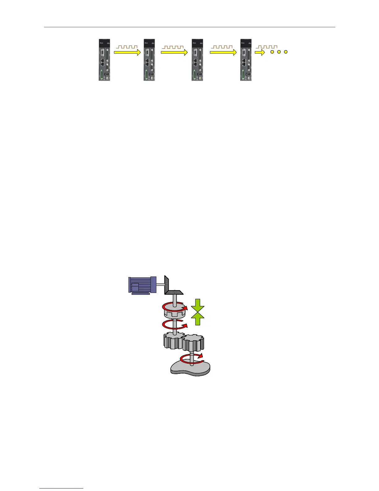
Cam
Engaged
P5-88.Z
Figure 2.8 Engaging of E-Cam
Shown in Figure 2.8, when E-Cam is engaged, the master axis will drive the slave axis via the
clutch and make it operate.

 Loading...


