Introduction of E-Cam Operation ASDA Series Application Note
2-6 March, 2015
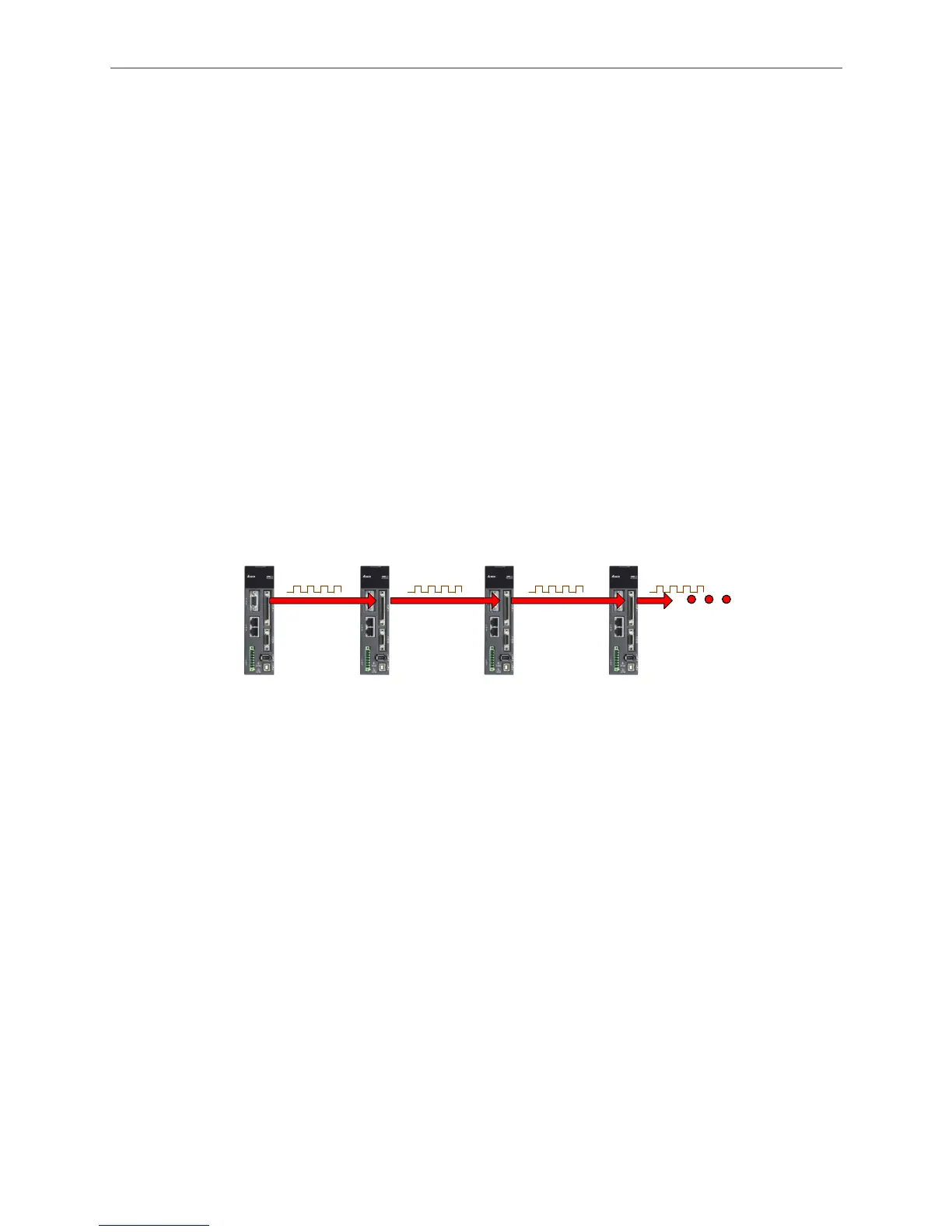
Pulse By-pass Function
On ASDA-A2, the by-pass function allows one master axis to drive multiple slave axes. With this
function, a servo can send the received signals to the next slave axis (servo). Signals passing
through the servo will not be attenuated because ASDA-A2 acts like an amplifier, boosting the
signal and maintain its origin intensity before output. For example, the input signal of 4.5 V will be
amplified to 5 V when output. However, signal attenuation during transmission via cables shall be
taken into consideration (because of the resistor in the cable). If the signal is attenuated to an
extent that cannot be identified by the input terminal, strengthening or shortening the cable is
required. Please be aware of this issue when wiring two servo drives; shielded twisted-pair is
suggested in this case. Regardless the signal delay, the signal transmission time of every
ASDA-A2 servo drive is only 50n second. That is, when 10 ASDA-A2 servos are serial
connected and transmit pulses with by-pass function, the input lag between the first servo drive
and the tenth is 0.5u second.
Although the only pin for pulse input on ASDA-A2 is OA, /OA, OB, /OB of CN1, pulses can also
be input via CN1 or CN5. The source of input signal can be specified by P1-74.B. Thus, when
using by-pass function and to use CN1 as the pulse input channel (shown in Figure 2.6), P1-74.B
is set to 2 for each slave axis (servo) so the servo will output the signal received from CN1.
Master
CN1
OA,
/OA,
OB,
/OB
CN1
Pulse,
/Pulse,
Sign,
/Sign
Slave 1
CN1
OA,
/OA,
OB,
/OB
Slave 2
CN1
Pulse,
/Pulse,
Sign,
/Sign
Slave 2
CN1
OA,
/OA,
OB,
/OB
Slave 3
CN1
Pulse,
/Pulse,
Sign,
/Sign
Slave 3
CN1
OA,
/OA,
OB,
/OB
P1-74.B = 2
P1-74.B = 2P1-74.B = 2
CN1
OA,
/OA,
OB,
/OB
Slave 1
CN1
Pulse,
/Pulse,
Sign,
/Sign
CN1
OA,
/OA,
OB,
/OB
CN1
Pulse,
/Pulse,
Sign,
/Sign
CN1
OA,
/OA,
OB,
/OB
CN1
Pulse,
/Pulse,
Sign,
/Sign
CN1
OA,
/OA,
OB,
/OB
P1-74.B =
P1-74.B = P1-74.B =
Figure 2.6 Pulse By-pass Function: CN1 IN / CN1 OUT
When wiring, users may use CN5 as the input channel. See Figure 2.7, P1-74.B is set to 1 on
every slave axis (servo); these servos will output signals received from CN5.

 Loading...


