ASDA Series Application Note Application Examples
March, 2015 3-55
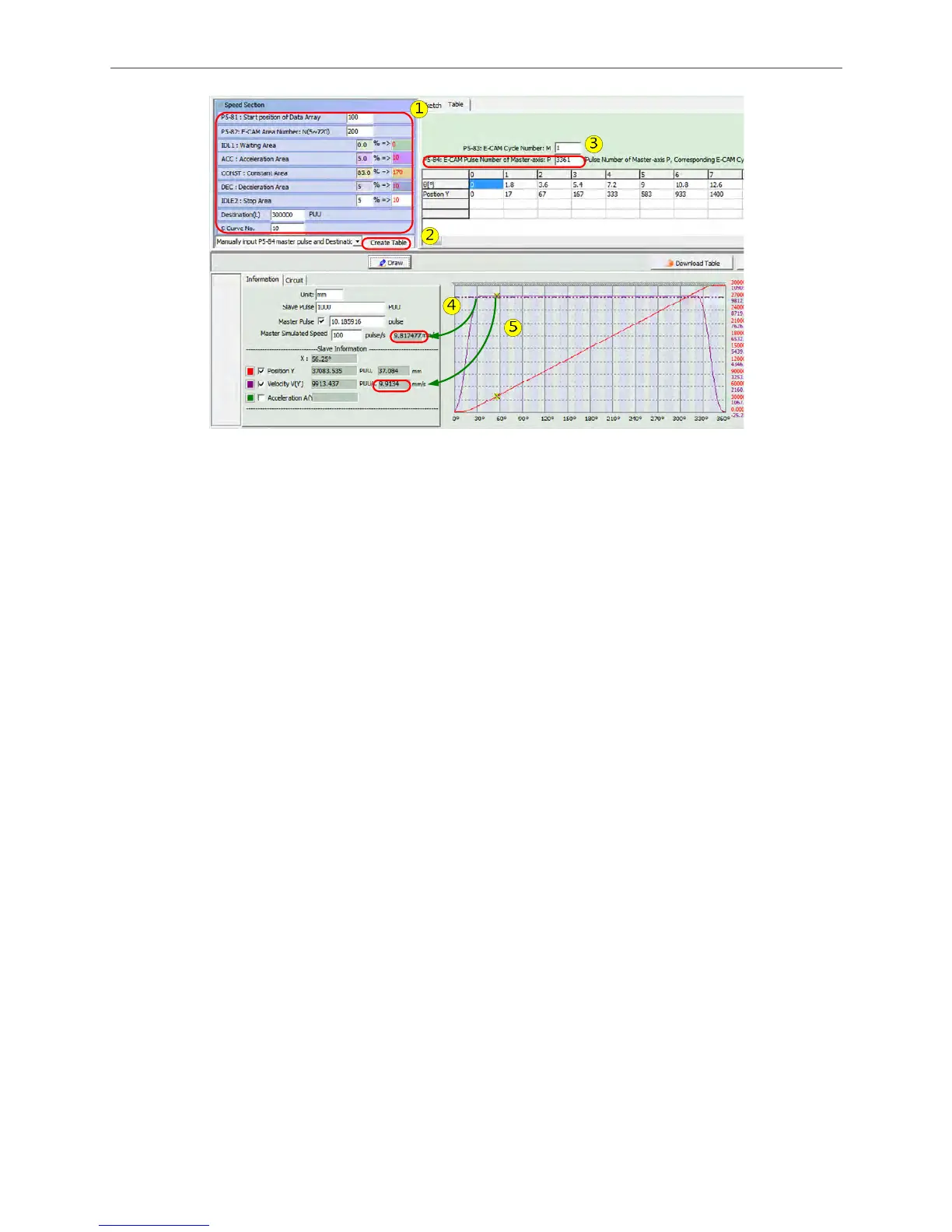
Figure 3.3.22 Adjust the E-cam curve of master axis lead
3.3.3.6 Analysis of E-cam Curve
In Figure 3.3.23, mark 5 shows the traveling distance of master axis and camshaft axis at 30°
(before entering the Constant Speed Area).
Master axis: 3376*(30/360) = 281.333 (pulse), 281.333 / 10.185916 (Figure 3.3.23, mark 4) =
27.62 mm.
Slave axis (Move the cursor to 30° and access the position field): 15744.672 (Figure 3.3.23,
mark 5) / 1000 (Figure 3.3.23, mark 4) = 15.74 mm.
From the above calculation, master axis travels 27.62 mm while slave axis only travels 15.74 mm
before entering the Constant Speed Area. The difference between both influence the position of
labeling start sensor, see Figure 3.3.24.
Before the camshaft enters the Constant Speed Area, it will travel 15.74 mm. If the highest
speed of master axis is S (the highest speed the labeling machine could operate), then it will take
T time (= 27.62/S) to travel 27.62 mm. Before entering the Constant Speed Area, the
acceleration A of camshaft axis in Acceleration Area is:
A (Acceleration) = (S (target speed) – 0 (accelerate from 0) / T
α (angular acceleration)= A / r (rotary shaft radius)
T (torque) = J (inertia) *α (angular acceleration)
From the above calculation, T (the torque needed during acceleration) can see if this E-cam
curve can meet the requirements or not.

 Loading...


