Application Examples ASDA Series Application Note
3-34 March, 2015
3.2.3.5 System Adjustment
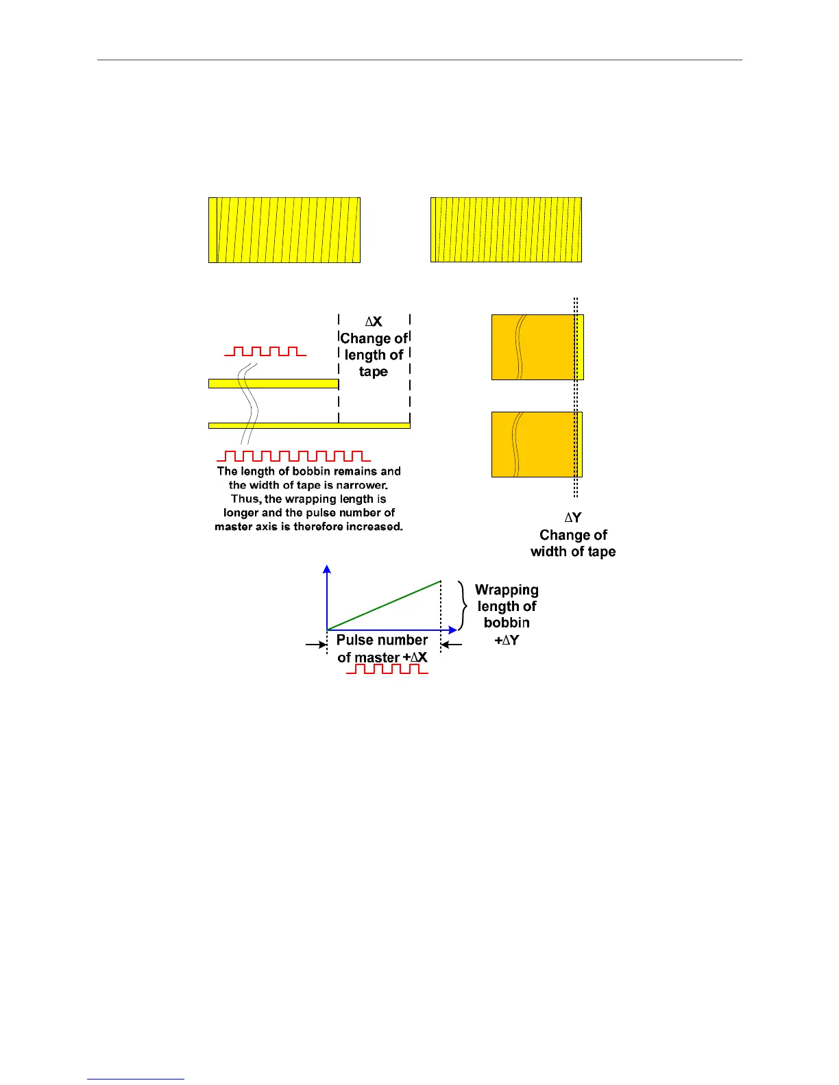
a. The length of bobbin remains and the width of tape is changed.
See Figure 3.2.20. Assume the tape is changed from 15 mm to 10 mm and the interval and the
length of bobbin remain at 0.2 mm and 190 mm respectively.
Figure 3.2.20 Change of tape width
∆Y, adjust the parameter of E-cam distance:
190mm – 10.2mm=179.8 mm;
179.8mm / 5 (mm/rev) = 35.96 rev, the cycle the ball screw travels;
35.96 * 2 =71.92 rev, converse to motor by E-cam;
PR#2: P5-19=71.92.
∆X, adjust the pulse number sent by master axis:
190mm / (10mm + 0.2mm) =18.62745 cycles;
(18.62745-1)cycle* 14400 (pulse/cycle) =253835 pulse;
PR#4: P5-84=253835/2=126917;
PR#5: P5-89=126917;
PR#11: P5-84=253835;
PR#12: P5-89=253835.

 Loading...


