EasyManua.ls Logo

Digi XBee3 802.15.4 User Manual

Digi XBee3 802.15.4
185 pages
To Next Page IconTo Next Page
To Previous Page IconTo Previous Page
Page #33 background imageLoading...
Page #33 background image
Serial communication Serial interface
Digi XBee3® 802.15.4 RF Module User Guide
33
Serial interface
The XBee3 802.15.4 RF Module interfaces to a host device through a serial port. The device can
communicate through its serial port:
n Through logic and voltage compatible universal asynchronous receiver/transmitter (UART).
n Through a level translator to any serial device, for example through an RS-232 or USB interface
board.
n Through SPI, as described in SPI communications.
Serial receive buffer
When serial data enters the device through the DIN pin or the SPI_MOSI pin, it stores the data in the
serial receive buffer until the device can process it. Under certain conditions, the device may not be
able to process data in the serial receive buffer immediately. If large amounts of serial data are sent
to the device such that the serial receive buffer overflows, then the device discards all incoming data
until it is able to process the data in the buffer. If the UART is in use, you can avoid this by the host side
by honoring clear-to-send (CTS) flow control.
Serial transmit buffer
When the device receives RF data, it moves the data into the serial transmit buffer and sends it out
the UART. If the serial transmit buffer becomes full and the system buffers are also full, then it drops
the entire RF data packet. Whenever the device receives data faster than it can process and transmit
the data out the serial port, there is a potential of dropping data.
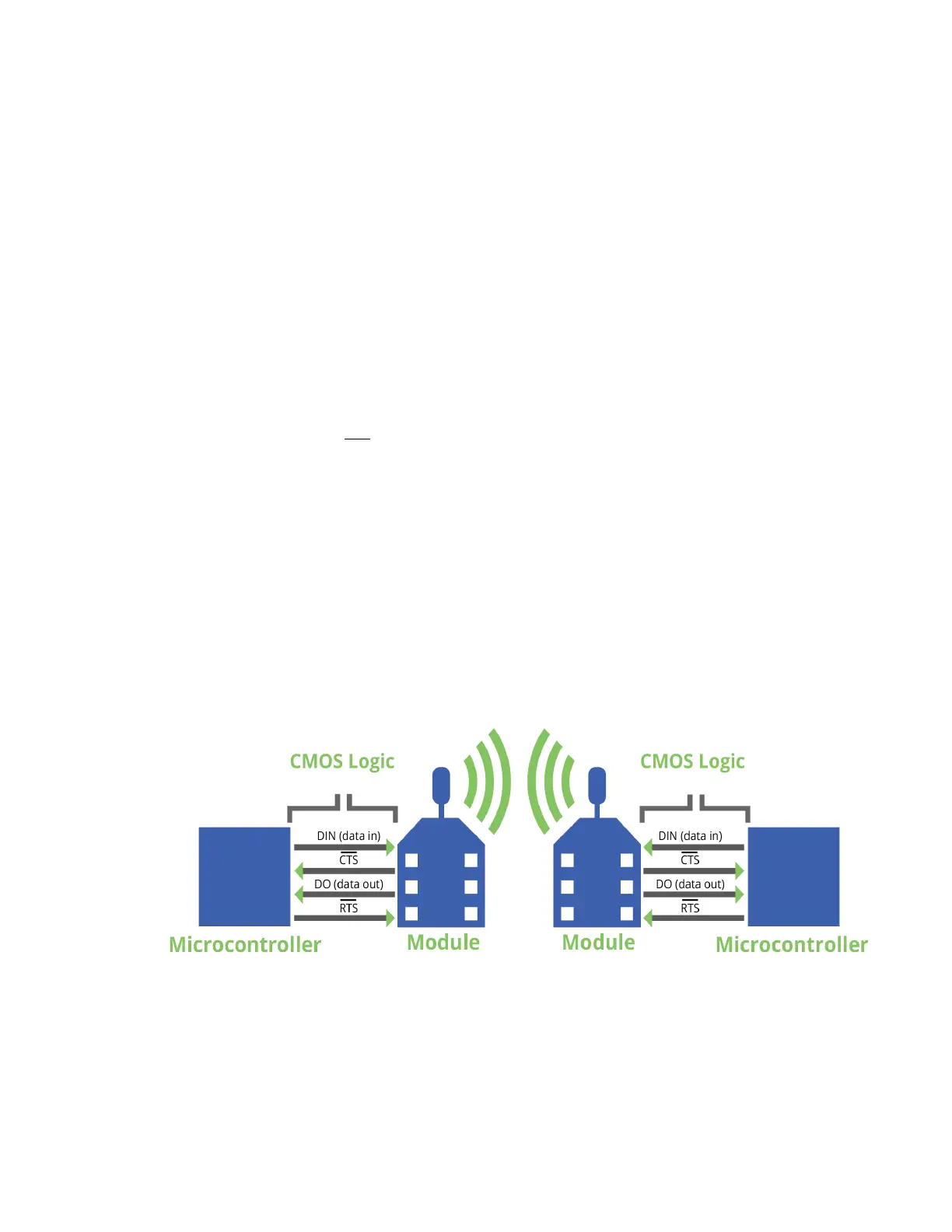
UART data flow
Devices that have a UART interface connect directly to the pins of the XBee3 802.15.4 RF Module as
shown in the following figure. The figure shows system data flow in a UART-interfaced environment.
Low-asserted signals have a horizontal line over the signal name.
For more information about hardware specifications for the UART, see the XBee3 Hardware Reference
Manual.
Serial data
A device sends data to the XBee3 802.15.4 RF Module's UART as an asynchronous serial signal. When
the device is not transmitting data, the signals should idle high.

Table of Contents

Question and Answer IconNeed help?

Do you have a question about the Digi XBee3 802.15.4 and is the answer not in the manual?

Digi XBee3 802.15.4 Specifications

General IconGeneral
Module TypeXBee3
Protocol802.15.4
Frequency Band2.4 GHz
Data RateUp to 250 kbps
Range (Line of Sight)1200 m
Operating Temperature-40° C to +85° C
SecurityAES-128
I/O InterfacesUART, SPI, I2C
Antenna OptionsU.FL
Power Supply2.1 to 3.6 VDC

Summary

Trademarks and Copyright

Disclaimers

Warranty

Customer Support

Applicable Firmware and Hardware

Firmware Support

Information on supported firmware versions for the module.

Hardware Support

Details on the compatible hardware versions for the module.

Get Started

Verify Kit Contents

Lists the components included in the XBee3 development kit.

Assemble the Hardware

Instructions for assembling and disassembling hardware components.

Configure the Device Using XCTU

Steps for configuring the device using the XBee Configuration and Test Utility.

Perform a Range Test

Procedure for testing RF range and link quality between two modules.

Configure the XBee3 802.15.4 RF Module

Over-the-Air (OTA) Firmware Update

Instructions for updating firmware remotely using XCTU.

Custom Defaults

How to set and manage custom default device configurations.

Modes

Transparent Operating Mode

Device behavior as a serial line replacement for RF transmission.

API Operating Mode

Structured interface for complex communication using packets.

Command Mode

State for interacting with the device via AT commands for configuration.

Serial Communication

Serial Interface

How the module interfaces with host devices via UART or SPI.

Flow Control

Mechanisms to manage data flow and prevent buffer overflow.

SPI Operation

SPI Communications

Details on SPI signals, directions, and functions in slave mode.

Low Power Operation

How sleep modes function with SPI and UART interfaces.

I/O Support

Digital I/O Support

Configuration of digital I/O lines for input, output, and sampling.

Analog I/O Support

Configuration of analog inputs for sampling and PWM outputs.

Periodic I/O Sampling

How to sample I/O pins at a periodic rate.

Digital I/O Change Detection

Triggering samples based on digital pin state changes.

Networking

MAC Mode Configuration

Settings for Digi header and MAC acknowledgments.

Addressing

How source and destination addresses are handled in RF packets.

Encryption

Enabling and controlling AES 128-bit encryption for RF transmissions.

Maximum Payload

Factors affecting the maximum data payload size in packets.

Sleep Support

Sleep Modes

Configurations for Pin Sleep, Cyclic Sleep, and Pin Wake-up modes.

Sleep Parameters

AT commands related to sleep mode configuration and timing.

Sleep Conditions

Factors that prevent the device from entering sleep mode.

AT Commands

Network and Security Commands

Commands for network channel, ID, security, and compatibility settings.

802.15.4 Addressing Commands

Commands for setting source, destination, and network addresses.

UART Interface Commands

Commands for configuring serial communication parameters.

I/O Settings Commands

Commands for configuring the module's digital and analog I/O pins.

I/O Sampling Commands

Commands for reading I/O pin states and generating sample data.

Operate in API Mode

API Mode Overview

Benefits and structure of API mode for device communication.

API Frame Format

Structure and fields of API frames for data exchange.

Frame Descriptions

TX Request: 64-bit Address Frame - 0x00

Frame for sending data to a specific 64-bit address.

AT Command Frame - 0x08

Frame for querying or setting local AT command parameters.

RX Packet: 64-bit Address Frame - 0x80

Frame indicating receipt of data via 64-bit addressing.

AT Command Response Frame - 0x88

Frame indicating the result of an AT Command request.

TX Status Frame - 0x89

Frame indicating the status of a transmitted packet.

OTA Firmware Upgrade Process for 802.15.4

OTA/OTB File

Structure and format of OTA firmware image files.

Create the Image Notify Request

Frame used to inform the client about an available firmware update.

Query Next Image Request

Client request for the next firmware image block.

Image Block Request

Client request for specific bytes of the OTA firmware image.

OTA Error Handling

Troubleshooting common errors during the OTA upgrade process.

Related product manuals