I/O support Digital line passing
Digi XBee3® 802.15.4 RF Module User Guide
55
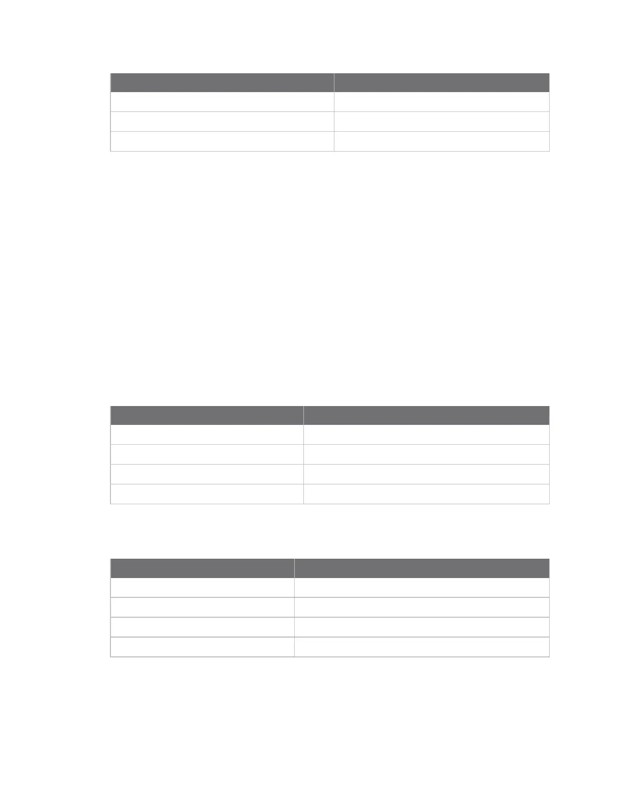
AT command Parameter value
D2 command 5 (digital output low)
T2 command 0x64 (10 seconds)
IA (I/O Input Address) 0013A20087654321
When this device receives an incoming I/O sample, if the source address matches the one set byIA,
the device sets the output ofD2to match the input ofD2of the receiver. This output level holds for
ten seconds before the pin returns to a digital output low state.
Analog line passing
Similar to digital line passing, analog line passing pairs the Analog I/O support of one device to a PWM
output of another. There are two PWM output pins that can simulate the voltage measured by the
ADC inputs. Be aware that ADC inputs are on different pins than the corresponding PWM outputs: AD0
corresponds to PWM0, and AD1 corresponds to PWM1. See Analog I/O support for the pinouts.
You can set the analog line passing timeout value withPT (PWM Output Timeout), which affects both
PWM output pins. You can explicitly set a PWM output level using theM0 commandandM1
commandcommands, when an I/O sample is received that affects a PWM output pin, it returns to its
configured state after thePTtimeout period expires.
Example:Analog line passing
A sampling device is configured with the following settings:
AT command Parameter value
DO command 2 (ADC input)
IR command 0x7D0 (2 seconds)
DH command 0013A200
DL command 12345678
Every two seconds, an I/O sample frame is generated and sent to the address specified by DH and DL.
The receiver is configured with the following settings:
AT command Parameter value
P0 2 (PWM output)
M0 0
PT 0x12C (30 seconds)
IA 0013A20087654321
When this device receives an incoming I/O sample, if the source address matches the one set byIA,
the device sets the PWM output ofP0to match the ADC input ofD0of the receiver. This output level
holds for thirty seconds before the pin returns to a digital output low state.
 Loading...


