I/O support I/O line passing
Digi XBee3® 802.15.4 RF Module User Guide
54
Note Use caution when combining change detect sampling with sleep modes.IC only causes a sample
to be generated if a state change occurs during a wake period. If the device is sleeping when the
digital transition occurs, then no change is detected and an I/O sample is not generated.
Use periodic sampling withIRin conjunction withICin this instance, sinceIRgenerates an I/O sample
upon wakeup and ensures that the change is properly observed.
If you enable multiple samples by settingIT> 1, any change detect that occurs causes all collected
periodic samples to be sent immediately, then a separateICsample is sent.
I/O line passing
Line passing allows you to affect the output pins of one device by sampling the I/O pins of another. To
support line passing, you must configure a device to generate I/O sample data using periodic sampling
(IR command) and/or change detection (IC command).
On the device that receives I/O samples, enable line passing setting IA (I/O Input Address) with the
address of the device that has the appropriate inputs enabled. This effectively binds the outputs to a
particular device’s input. This does not affect the ability of the device to receive I/O line data from
other devices—only its ability to update enabled outputs. Set IA to 0xFFFF (broadcast address) to
affect the output using input data from any device on the network.
Digital line passing
Digital I/O lines are mapped in pairs; pins configured as digital input on the transmitting device affect
the corresponding digital output pin on the receiving device. For example, a device that samplesD5as
an input (3) only affectsD5on the receiver ifD5is configured as an output (4 or 5).
Each digital pin has an associated timeout value. When an I/O sample is received that affects a digital
output pin, the pin returns to its configured state after the timeout period expires. For
pinsD0throughD9, the associated timeout commands areT0 commandthroughT9 command. For
pinsP0throughP4, the associated timeout commands are Q0 commandthroughQ4.
Digital line passing is only available on pinsD0throughP3. You cannot use UART and SPI pins for line
passing.
Example:Digital line passing
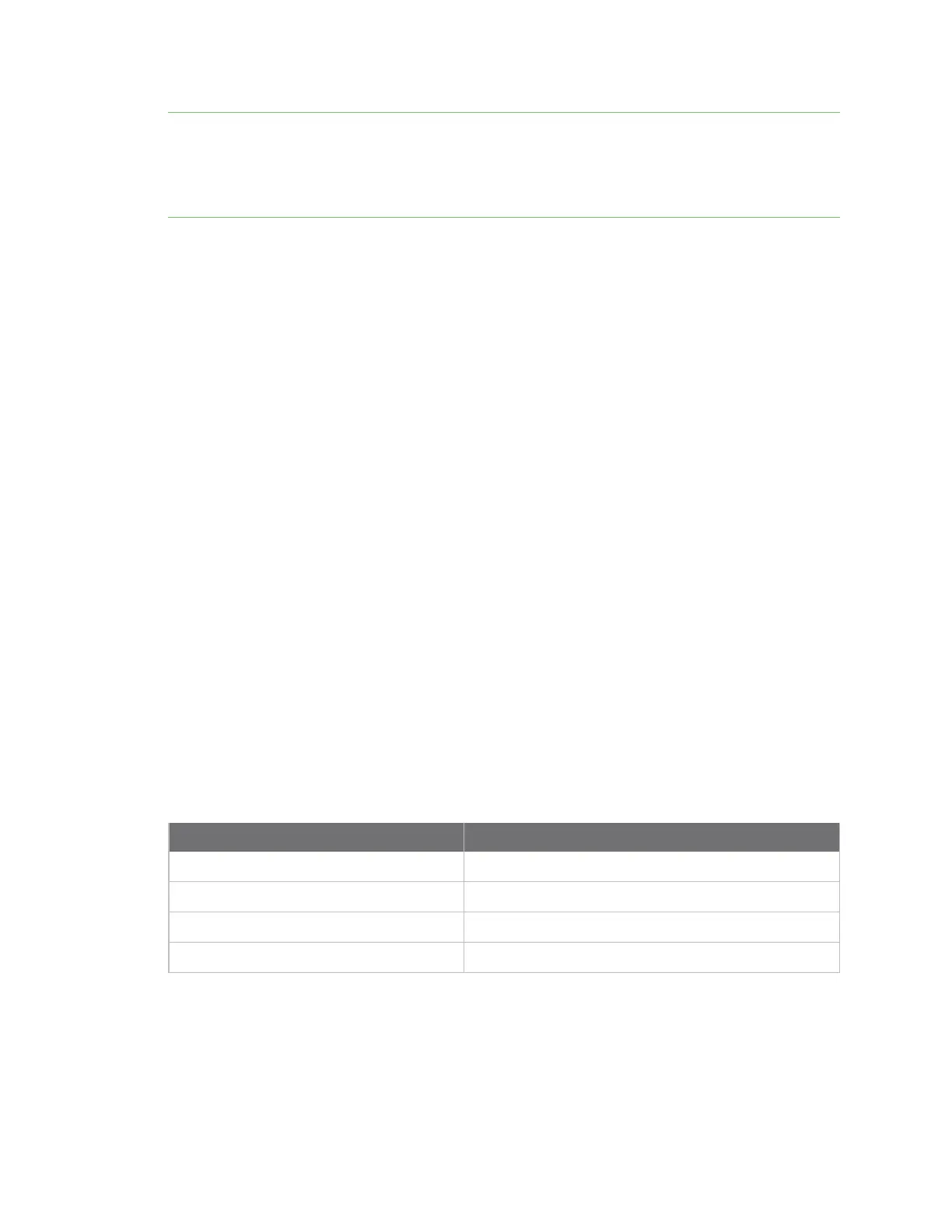
A sampling XBee3 802.15.4 RF Module is configured with the following settings:
AT command Parameter value
D2 command 3 (digital input)
IR command 0x7D0 (2 seconds)
DH command 0013A200
DL command 12345678
Every two seconds, an I/O sample is generated and sent to the address specified by DH and DL. The
receiver is configured with the following settings:
 Loading...


