EasyManua.ls Logo

Digi XBee3 802.15.4 User Manual

Digi XBee3 802.15.4
185 pages
To Next Page IconTo Next Page
To Previous Page IconTo Previous Page
Page #42 background imageLoading...
Page #42 background image
I/O support Legacy support
Digi XBee3® 802.15.4 RF Module User Guide
42
Legacy support
By default, the XBee3 802.15.4 RF Module is configured to operate in a legacy configuration. This
provides network and application compatibility withXBee S1 802.15.4andXBee S2C
802.15.4devices.Use AO command to determine which outgoing API frames are emitted and what
I/O lines are used for sampling.
On the source node,AOaffects:
n Which Digital I/O lines are sampled
n What sample frame type is used for outgoing transmissions
On the destination node,AOaffects:
n How incoming XBee3 sample frames are interpreted and what API frames are emitted
Previous 802.15.4 firmwares on the XBee S1 and XBee S2C hardware had a limited set of I/O lines
available. Valid DIO lines on these devices are fromD0throughD8; I/O samples are transmitted over
the air using a standard I/O sample packet Legacy data format. These platforms do not have
anAOcommand and always output sample data in a legacy format if possible.
For the XBee3 platform, digital I/O has been enhanced to be in parity with DigiMesh and Zigbee. You
can now enable up to fourteen digital inputs for sampling:D0throughP4as long asAOis not set to 2.
In order to support these additional I/O lines, an enhanced I/O sample packet is sent over the air,
which is not compatible with the S1 or S2C.
By default, the XBee3 802.15.4 RF Module is configured to operate in a legacy configuration
withAOset to 2. This allows you to sampleD0throughD8. Ifyou configure D9throughP4 as digital
I/O, they are not sampled unlessyou set AOto 0 or 1.
For new designs, we recommend settingAOto 0 or 1 (Operate in API mode), which allows you to use
additional I/O lines for sampling and easily allows you to switch to Zigbee or DigiMesh, as the API and
I/O functionality are identical.
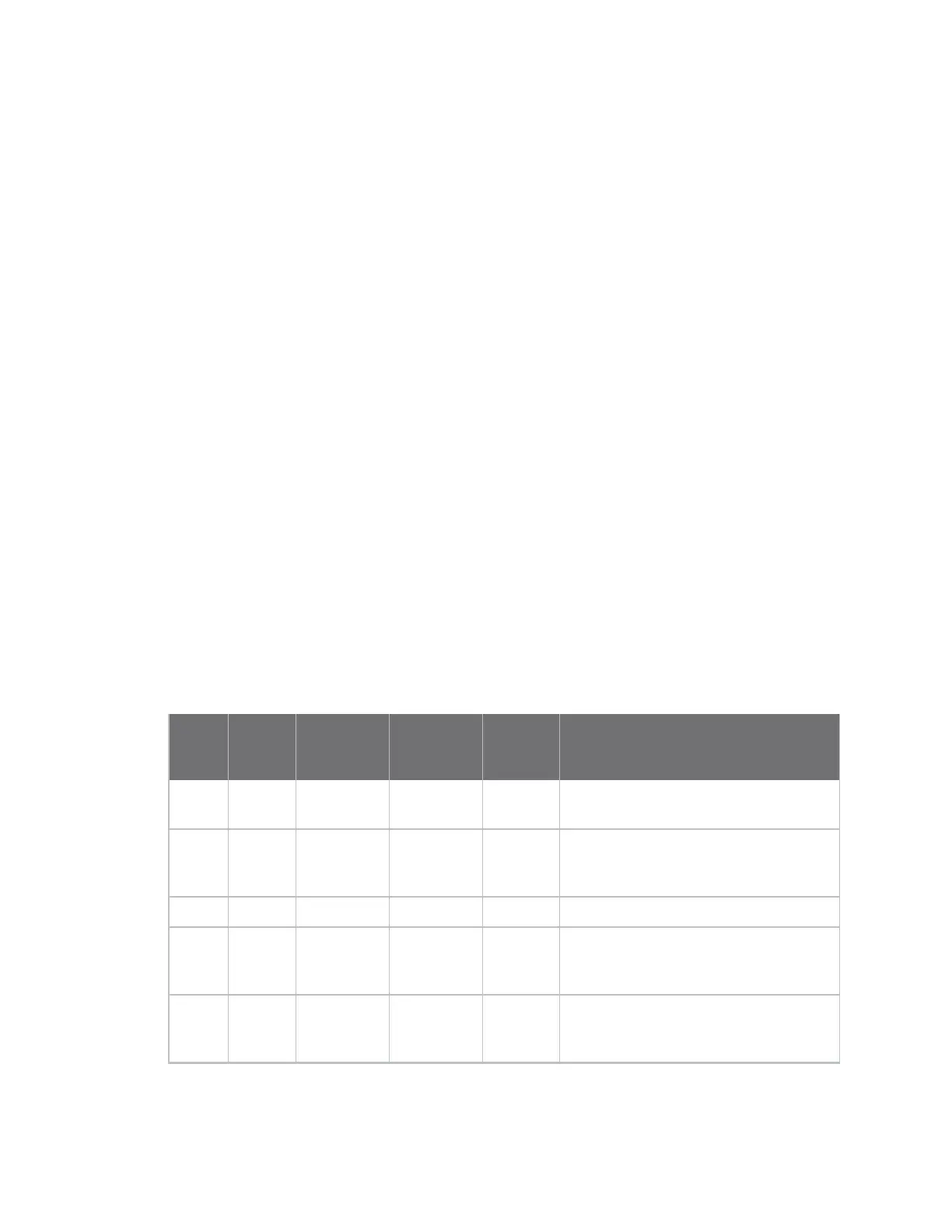
This table illustrates the various configuration combinations that are possible and the expected
output:
Source
Source
AO
value Destination
Destination
AO value
Data
format API frame on receiver
XBee3 0 or 1 XBee3 0 or 1 Enhanced I/O Data Sample Rx Indicator frame -
0x92
XBee3 0 or 1 XBee3 2 Legacy RX (Receive) Packet: 64-bit address IO
frame - 0x82 / RX Packet: 16-bit address
I/O frame - 0x83
XBee3 0 or 1 S1 or S2C N/A N/A N/A
XBee3 2 XBee3 0 or 1 Legacy RX (Receive) Packet: 64-bit address IO
frame - 0x82 / RX Packet: 16-bit address
I/O frame - 0x83
XBee3 2 S1 or S2C N/A Legacy RX (Receive) Packet: 64-bit address IO
frame - 0x82 / RX Packet: 16-bit address
I/O frame - 0x83

Table of Contents

Question and Answer IconNeed help?

Do you have a question about the Digi XBee3 802.15.4 and is the answer not in the manual?

Digi XBee3 802.15.4 Specifications

General IconGeneral
Module TypeXBee3
Protocol802.15.4
Frequency Band2.4 GHz
Data RateUp to 250 kbps
Range (Line of Sight)1200 m
Operating Temperature-40° C to +85° C
SecurityAES-128
I/O InterfacesUART, SPI, I2C
Antenna OptionsU.FL
Power Supply2.1 to 3.6 VDC

Summary

Trademarks and Copyright

Disclaimers

Warranty

Customer Support

Applicable Firmware and Hardware

Firmware Support

Information on supported firmware versions for the module.

Hardware Support

Details on the compatible hardware versions for the module.

Get Started

Verify Kit Contents

Lists the components included in the XBee3 development kit.

Assemble the Hardware

Instructions for assembling and disassembling hardware components.

Configure the Device Using XCTU

Steps for configuring the device using the XBee Configuration and Test Utility.

Perform a Range Test

Procedure for testing RF range and link quality between two modules.

Configure the XBee3 802.15.4 RF Module

Over-the-Air (OTA) Firmware Update

Instructions for updating firmware remotely using XCTU.

Custom Defaults

How to set and manage custom default device configurations.

Modes

Transparent Operating Mode

Device behavior as a serial line replacement for RF transmission.

API Operating Mode

Structured interface for complex communication using packets.

Command Mode

State for interacting with the device via AT commands for configuration.

Serial Communication

Serial Interface

How the module interfaces with host devices via UART or SPI.

Flow Control

Mechanisms to manage data flow and prevent buffer overflow.

SPI Operation

SPI Communications

Details on SPI signals, directions, and functions in slave mode.

Low Power Operation

How sleep modes function with SPI and UART interfaces.

I/O Support

Digital I/O Support

Configuration of digital I/O lines for input, output, and sampling.

Analog I/O Support

Configuration of analog inputs for sampling and PWM outputs.

Periodic I/O Sampling

How to sample I/O pins at a periodic rate.

Digital I/O Change Detection

Triggering samples based on digital pin state changes.

Networking

MAC Mode Configuration

Settings for Digi header and MAC acknowledgments.

Addressing

How source and destination addresses are handled in RF packets.

Encryption

Enabling and controlling AES 128-bit encryption for RF transmissions.

Maximum Payload

Factors affecting the maximum data payload size in packets.

Sleep Support

Sleep Modes

Configurations for Pin Sleep, Cyclic Sleep, and Pin Wake-up modes.

Sleep Parameters

AT commands related to sleep mode configuration and timing.

Sleep Conditions

Factors that prevent the device from entering sleep mode.

AT Commands

Network and Security Commands

Commands for network channel, ID, security, and compatibility settings.

802.15.4 Addressing Commands

Commands for setting source, destination, and network addresses.

UART Interface Commands

Commands for configuring serial communication parameters.

I/O Settings Commands

Commands for configuring the module's digital and analog I/O pins.

I/O Sampling Commands

Commands for reading I/O pin states and generating sample data.

Operate in API Mode

API Mode Overview

Benefits and structure of API mode for device communication.

API Frame Format

Structure and fields of API frames for data exchange.

Frame Descriptions

TX Request: 64-bit Address Frame - 0x00

Frame for sending data to a specific 64-bit address.

AT Command Frame - 0x08

Frame for querying or setting local AT command parameters.

RX Packet: 64-bit Address Frame - 0x80

Frame indicating receipt of data via 64-bit addressing.

AT Command Response Frame - 0x88

Frame indicating the result of an AT Command request.

TX Status Frame - 0x89

Frame indicating the status of a transmitted packet.

OTA Firmware Upgrade Process for 802.15.4

OTA/OTB File

Structure and format of OTA firmware image files.

Create the Image Notify Request

Frame used to inform the client about an available firmware update.

Query Next Image Request

Client request for the next firmware image block.

Image Block Request

Client request for specific bytes of the OTA firmware image.

OTA Error Handling

Troubleshooting common errors during the OTA upgrade process.

Related product manuals