I/O support Analog I/O support
Digi XBee3® 802.15.4 RF Module User Guide
44
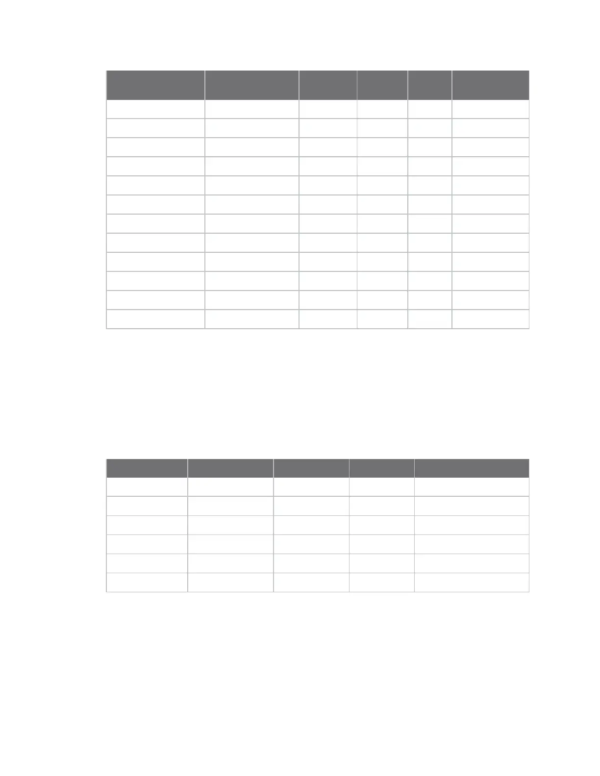
Function
whenAO= 0 or 1
Legacy Function
whenAO= 2 Micro Pin SMT Pin TH Pin AT Command
DIO3 DIO3 28 30 17 D3 command
DIO4 DIO4 23 24 11 D4 command
DIO5 DIO5 26 28 15 D5 command
DIO6 DIO6 27 29 16 D6 command
DIO7 DIO7 24 25 12 D7 command
DIO8 DIO8 9 10 9 D8 command
DIO9 N/A 25 26 13 D9 command
DIO10 N/A 7 7 6 P0 command
DIO11 N/A 8 8 7 P1 command
DIO12 N/A 5 5 4 P2 command
DIO13 N/A 3 3 2 P3 command
DIO14 N/A 4 4 3 P4 command
I\O sampling is not available for pinsP5throughP9. See the XBee3 Hardware Reference Manual for full
pinouts and functionality.
Analog I/O support
Analog input is available onD0throughD3. Configure these pins to 2 (ADC) to enable analog sampling.
PWM output is available onP0andP1,which can be used for Analog line passing.Use M0
commandandM1 command to set a fixed PWM level.
Function Micro Pin SMT Pin TH Pin AT Command
ADC0 31 33 20 D0 command
ADC1 30 32 19 D1 command
ADC2 29 31 18 D2 command
ADC3 28 30 17 D3 command
PWM0 7 7 6 P0 command
PWM1 8 8 7 P1 command
AV (Analog Voltage Reference) specifies the analog reference voltage used for the 10-bit ADCs. Analog
sample data is represented as a 2-byte value. For a 10-bit ADC, the acceptable range is from 0x0000
to 0x03FF. To convert this value to a useful voltage level, apply the following formula:
ADC / 1023 (vREF) = Voltage
 Loading...


