I/O support Digital I/O change detection
Digi XBee3® 802.15.4 RF Module User Guide
53
Output Field Description
00 04 Sample
set 1
The first set of digital sample data that corresponds with the digital portion of
the channel mask
0x0004 = 0000 0000 0000 0100b = DIO3 is high
01 28 Analog sample data for AD0
03 12 Analog sample data for AD1
00 00 Sample
set 2
The second set of digital sample data
0x0004 = 0000 0000 0000 0000b = DIO3 is low
01 58 Second set of analog sample data for AD0
02 FE Second set of analog sample data for AD1
00 04 Sample
set 1
The third set of digital sample data
0x0004 = 0000 0000 0000 0100b = DIO3 is high
01 2A Third set of analog sample data for AD0
03 A0 Third set of analog sample data for AD1
94 Checksum Can safely be discarded on received frames
Digital I/O change detection
You can configure devices to transmit a data sample immediately whenever a monitored digital I/O
pin changes state. IC command is a bitmask that determines which digital I/O lines to monitor for a
state change. If you set one or more bits inIC, the device transmits an I/O sample as soon it observes
a state change on the monitored digital I/O line(s) using edge detection.
Change detection is only applicable to digital I/O pins that are configured as digital input (3) or digital
output (4 or 5).
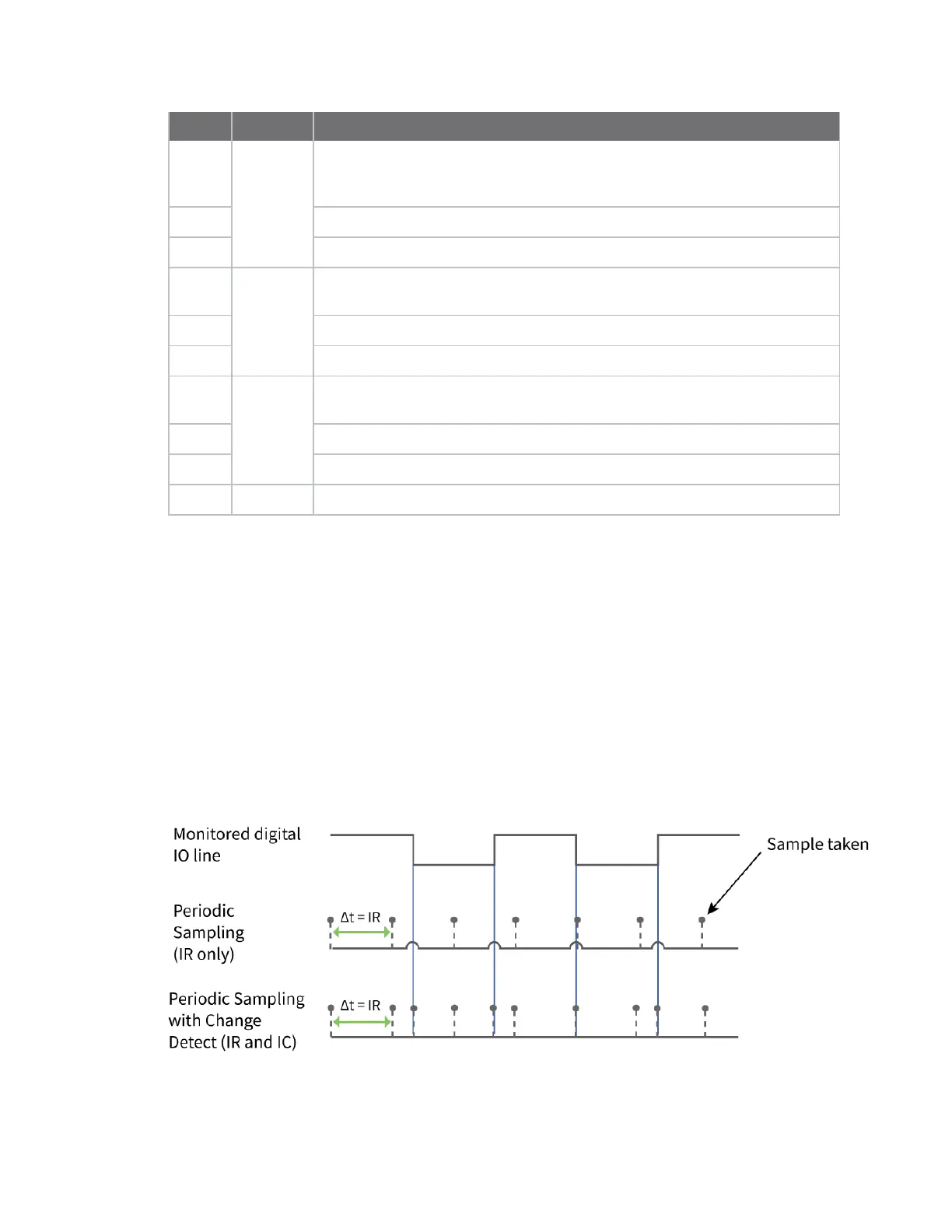
The figure below shows how I/O change detection can work in combination with Periodic I/O
sampling to improve sampling accuracy.In the figure, the gray dashed lines with a dot on top
represent samples taken from the monitored DIO line. The top graph shows only periodicIRsamples,
the bottom graph shows a combination ofIRperiodic samples andICdetected changes. In the top
graph, the humps indicate that the sample was not taken at that exact moment and needed to wait
for the nextIRsample period.