46 Installation and Service Guide
Replacing Parts
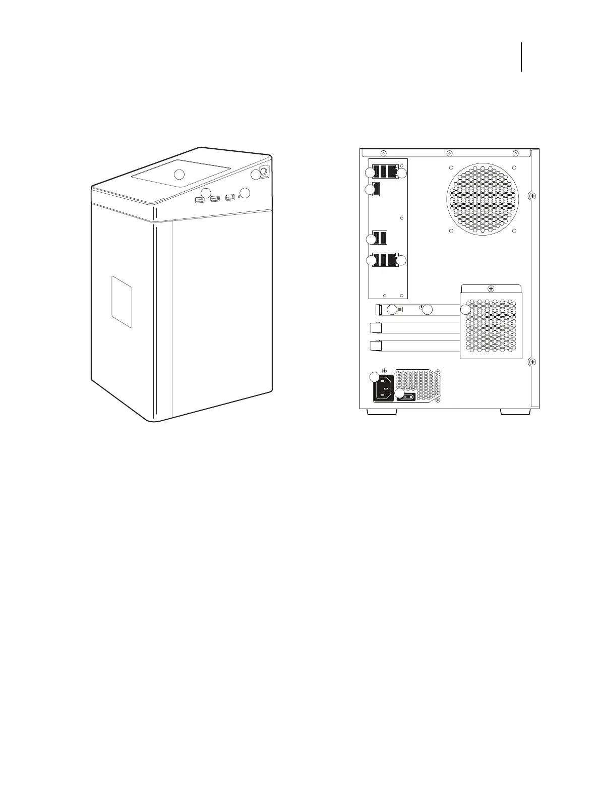
E-35A diagrams
The following figures provide an overview of E-35A components.
Figure 21: E-35A front and connector panel
Front panel Connector panel
1 Fiery QuickTouch LCD 5 Type A USB2.0 ports (x2)
2 Type A USB 3.0 ports (x3) 6 Network cable port (Upper RJ-45)
3 Reset button 7 Display port
4 Power button 8 Type A USB2.0 ports (x2)
Note: Do not use the USB ports on the Fiery QuickTouch
for keyboard/mouse connections for the service purpose.
Note: Unlabeled connectors/ports are not used.
9 Type A USB3.0 ports (x2)
10 Printer interface (Crossover Ethernet) cable port (Lower
RJ-45)
11 Type B USB port for power synchronization
12 OFF/ON switch for power synchronization
OFF: Left
ON: Right
13 Cover
14 Power connector
15 Power switch
|: Power On
O: Power Off

 Loading...
